Beretta 92FS/M9 Frame
Page
1 Page
2

For
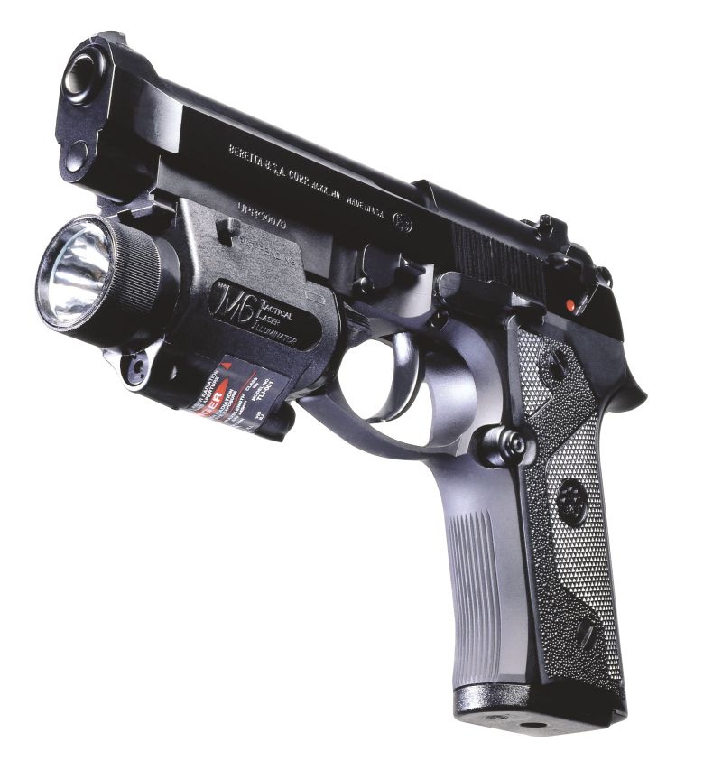
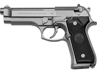
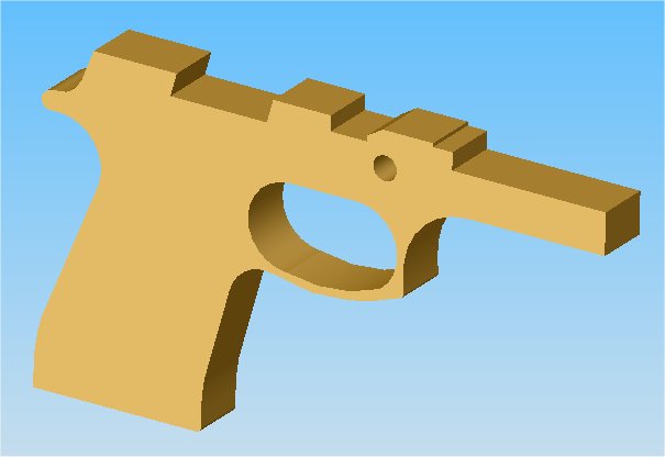
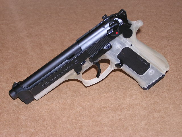
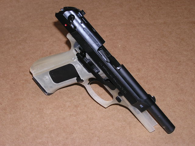
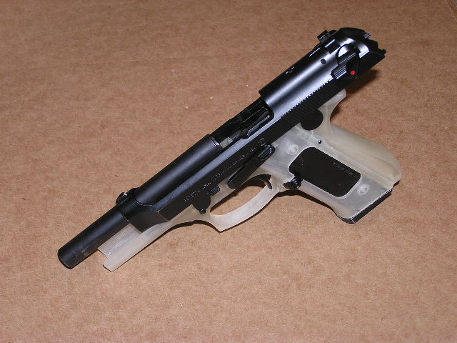
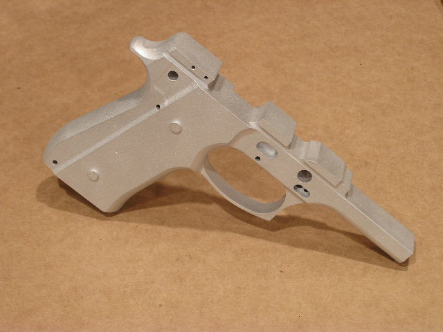
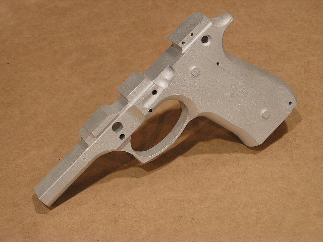
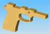
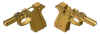
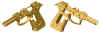
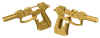
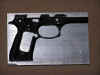
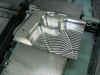
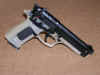
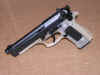
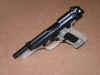
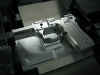
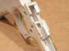
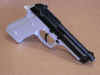
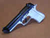
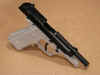
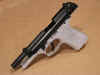
my next project, I will be doing the
Beretta 92FS frame. For those who
aren't familiar with this pistol, the
above pictures will give you an idea of
what it looks like. I recently purchased
a used (police trade-in) Beretta 92FS
pistol to use as a reference while I
make the solid model of the frame.
As of right now the only references I
have for this project is the pistol I
bought. I also have the drawing
below, but it doesn't give near enough
detail. I'm trying to get my hands
on any reference information that will
help me out while I'm working on the
solid model. So if anybody has any
useful information (blueprints, sketches,
etc.), please let me know. I would
really appreciate any help you can give
me to help this project take its first
steps.

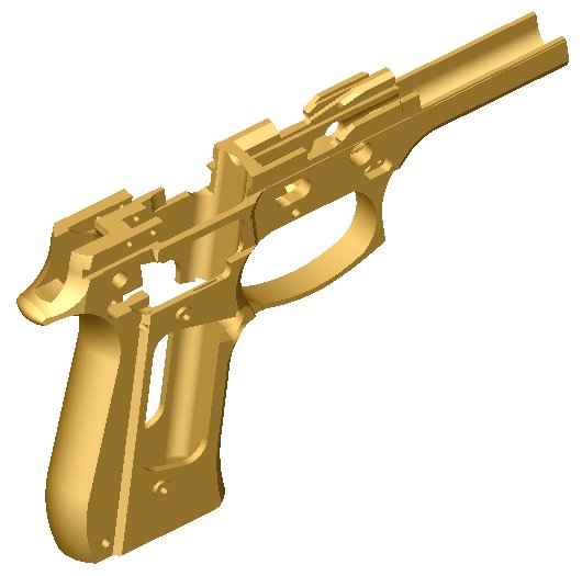
I
started to work on the solid model of
this project. So far I have the
rough profile of the pistol. Below
is a pic of what I have done so
far. If you have any information
you can share with me on this pistol I
would really appreciate it.
I
now have a pretty good start on the
solidmodel. I've been using the
Co-ordinate Measuring Machine (CMM)
at our shop to measure some of the
complex hole locations and
surfaces. Below you will see how
far along I am with this solidmodel.
I
got some more work done on the
solidmodel. About the only thing I
have left is the back of the frame where
the hammer slides in. Some of this
area is pretty complex, so it's going to
take some time to get all the
measurements and transfer that data to
the solidmodel. Below is what the
model now looks like.
I
now have the solidmodel
complete!!! I'm going to go back
and triple check all my measurements
before I start the machining to insure I
didn't make any mistakes. I
created a Solidworks E-drawing of this
frame if any of you would like to check
it out to see if I've missed any
features. Please let me know if
you find anything wrong. The E-drawing is located
under Downloads.
Below is what the final model looks
like.
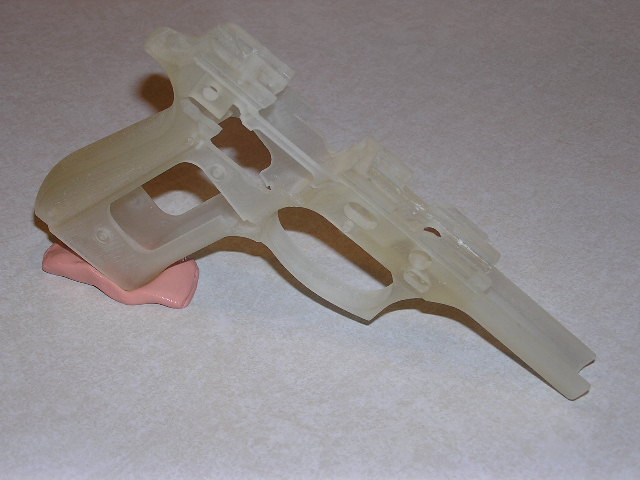
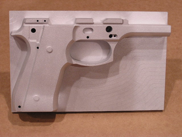
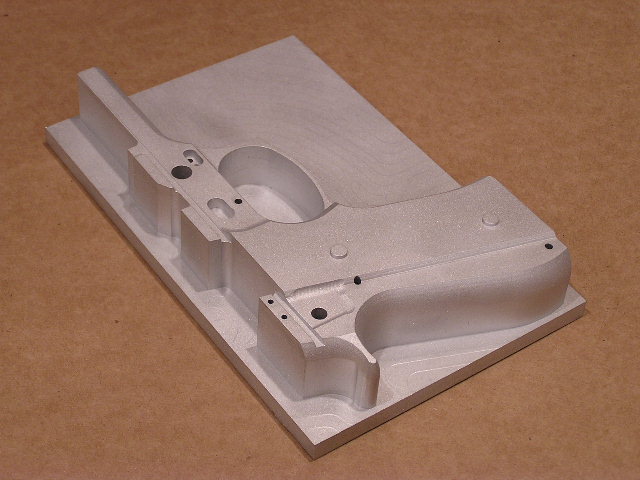
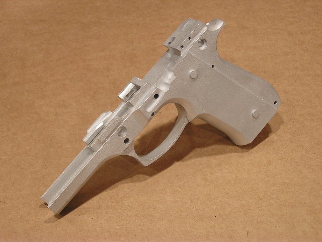
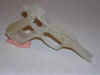
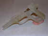
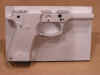
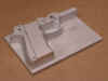
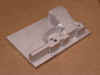
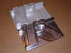
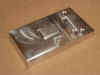
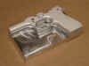
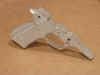
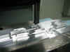
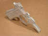
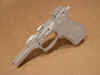
Since
I now have the solidmodel finished of
this frame, I decided to have it
"printed" out on a rapid
prototype machine also know as stereolithography.
Doing this will allow me to test fit
some of the parts, and insure my
solidmodel is correct before I start the
complicated machining process.
I've looked the prototype part over and
everything seems to be ok so far.
I'm now getting REALLY excited about
starting the machining of this
frame. Below you can see a couple
pics of what the "printed"
frame looks like. This frame is
made of a clear type of material so it
was hard to get a good picture, but
maybe you can get an idea of what it
looks like. I had to use some
"silly putty" to help stand
the part up for the pictures.
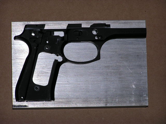
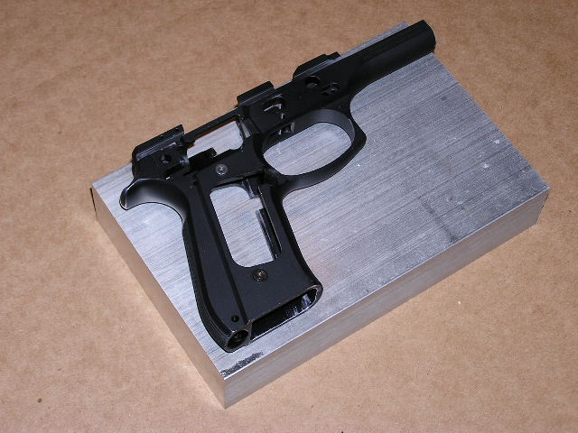
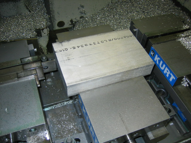
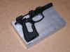
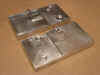
I
cut the aluminum blocks from a 12 foot
bar of 6061-T6 aluminum we had at the
shop. The dimension of the block
is 5" x 1�" x
7.760" Below you can see a
pic of my reference Beretta 92FS frame
setting on top of the aluminum
block. I stripped my Beretta 92FS
pistol down to just the bare frame, and
I used it to help make the
solidmodel. I hope to be able to
turn this 5.7 pound block of aluminum
into a working pistol frame.
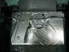
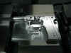
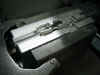
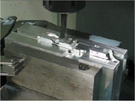
I
got the 1st operation programmed
for the CNC machining center. Here
is a picture of the block of material in
the machine ready to be machined...

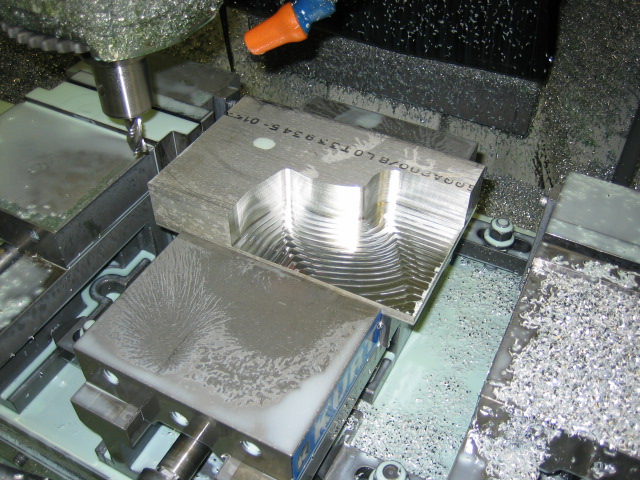
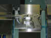
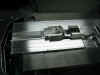
The
first tool to run was the 1/2" hog
end mill. This tool was used to
rough out most of the material. I
stopped the machine mid-way through this
tool to show how much material was being
removed...
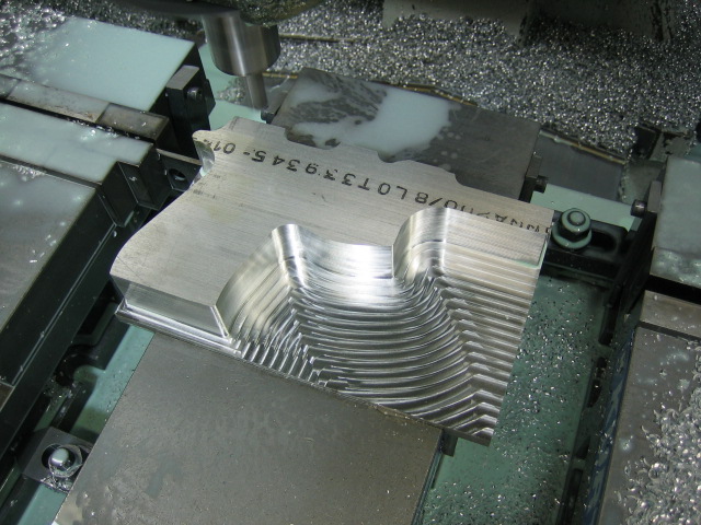
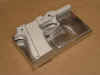
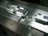
The
next picture I took was after the
outside profile had been roughed
out. You can see the block of
material is now taking the shape of the
pistol frame...
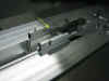
Below
is a pic after the 1/2" hog end
mill was finished roughing the frame...
You
can't really see it from the pictures,
but the 1/2" hog end mill leaves a
rough surface finish on the
material. So I used a 1/4"
carbide end mill to make the finish
passes around the frame. I used
the flash on the camera for this picture
to try and show how clean the outside of
the frame now looks...
The
next picture is after all the holes were
drilled...
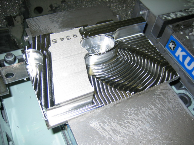
The
next tool to run was the 1/4" ball
nose carbide end mill. This is the
tool that can really turn a block of
material into a work of art. This
tool profiles across the whole frame by
machining square corners into smooth
surfaces. This tool takes a really
long time to run because it's machining
back and forth across the frame stepping
over 0.006" each time. This
tool made a total of 1260 passes back
and forth across the profile of the
frame. Below are a few pics
showing what the frame looked like after
this tool...
I
then ran a couple different smaller end
mills to finish up some minor details
and to cut the rail for where the slide
will fit. Here is what it looked
like after those tools...
That's
the end of the 1st operation.
There are some other cuts I could have
made on this operation, but I'm saving
those for further down the road.
If I made some of those cuts now, it
would have made the frame really weak
and hard to hold onto for future
operations. I bead blasted one of
the frames to reduce the glare in the
next pictures. Below are some
better pics, and the last pic is showing
the difference between the freshly
machine frame and the one that had been
bead blasted...
I
hope to find time to program and machine
the 2nd operation in the next few weeks.
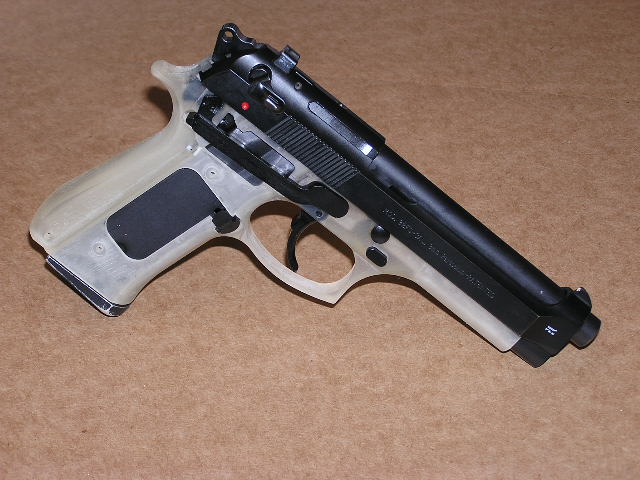
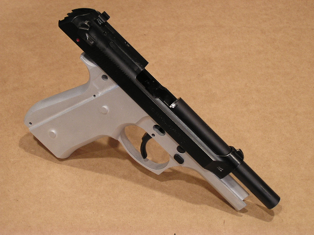
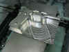
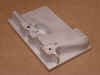
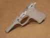
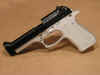
I
found time to test fit some of the parts
to the "printed" stereolithography
prototype frame. I didn't add all
the parts including some of the springs
because the plastic frame wouldn't be
able to withstand the forces put forth
by some of the springs. I didn't
find any problems assembling the parts
to the frame, so this far everything
looks good to go. Below are some
pretty cool pics of how the clear
plastic frame looks with the parts assembled...

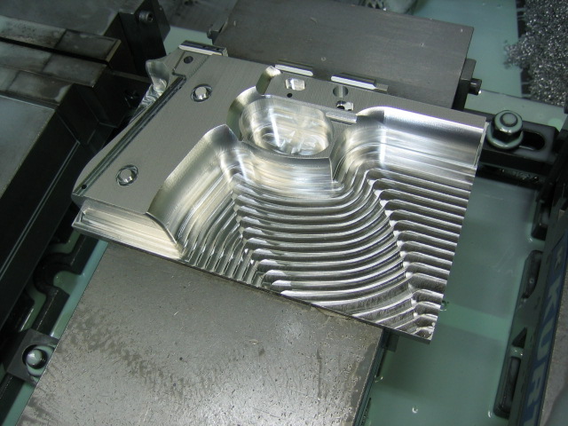
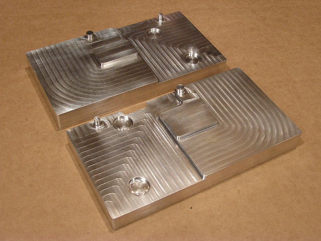
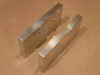
I
got the 2nd operation
machined. I had to make a special
fixture plate to hold the frame flat and
square while I done the machining.
I designed the fixture plate so I could
use it for both the left and right
machining processes. I also made
the plate to where it would touch as
many surfaces as possible, so it would
help keep the frame level during the
machining process. Below you can
see what the fixture plate looks like...
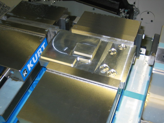
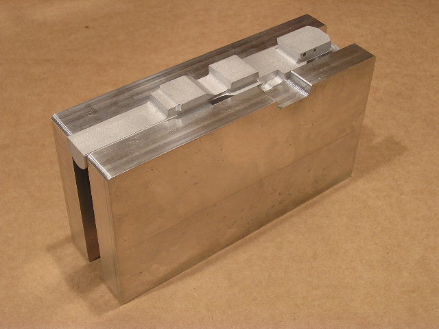
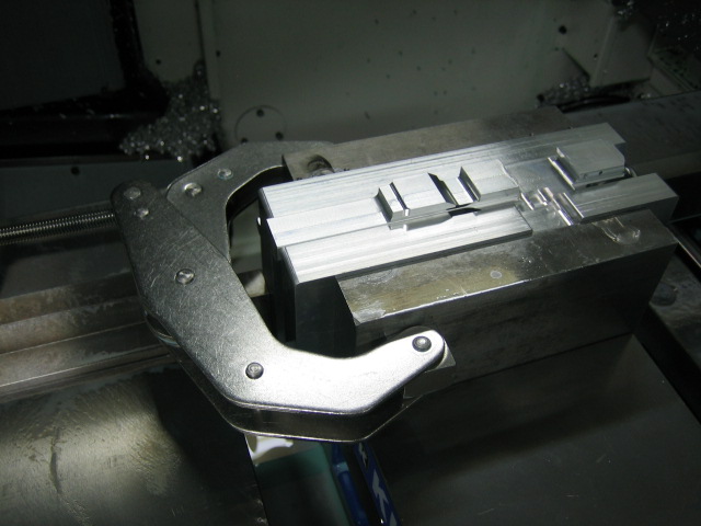
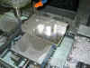
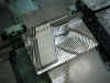
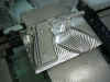
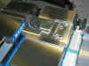
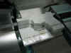
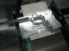
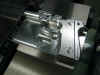
After
I got the fixture plate machined, it was
time to start machining the 2nd
operation on the frame. Below you
can see what the plate looked like in
the vise before I clamped in the pistol
frame...
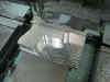
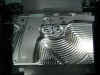
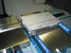
I
then clamped the frame in the vise and
used a machinist level to make sure the
frame was flat in both the "X"
and "Y" directions. The
plate worked perfectly, because
everything came out exactly level.
Below you can see what the frame looked
like before I started the machining
process...
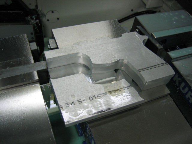
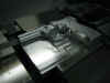
First
I used a 1/2" hog end mill to cut
around the outside of the frame to
remove the slab of material left over
from the 1st operation. Here you
can see what it looked like with the
slab removed...
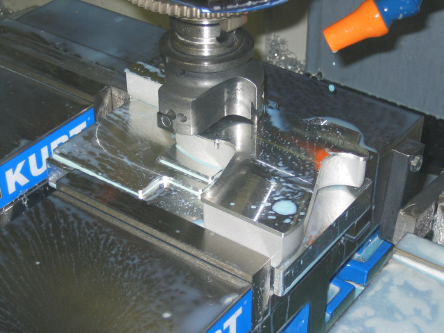
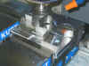
Next,
I used a 3" shell mill to bring the
frame to the correct thickness. I
stopped the shell mill while it was
cutting to take a picture to show
exactly what it was doing. You can
see this picture below and also the
picture after the shell mill was
finished cutting...
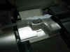
Then
I used the 1/2" hog end mill again
to rough most of the material away so I
could run the 3-D profiling process at a
faster feed rate. Here's a pic of
what it looked like after this tool ran
again...
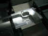
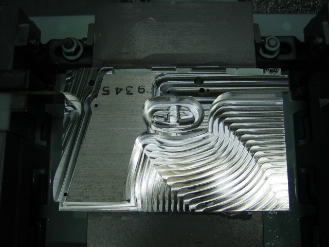
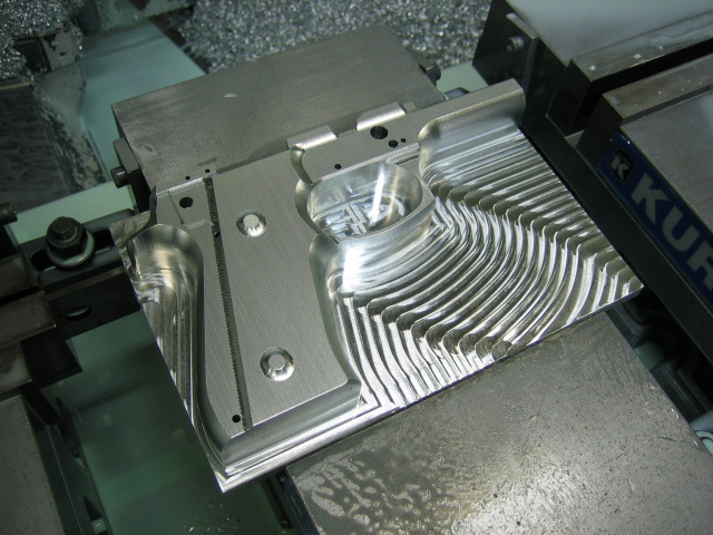
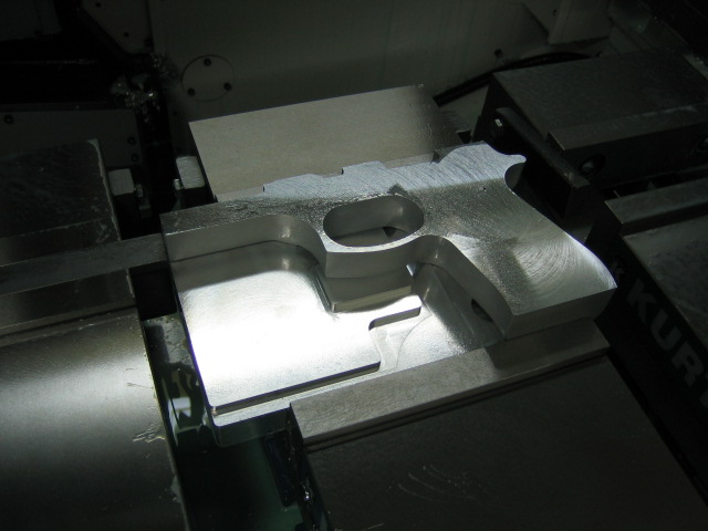
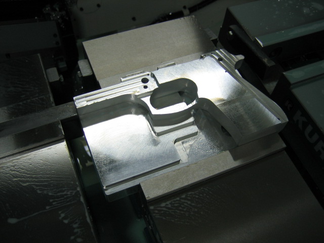
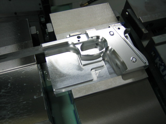
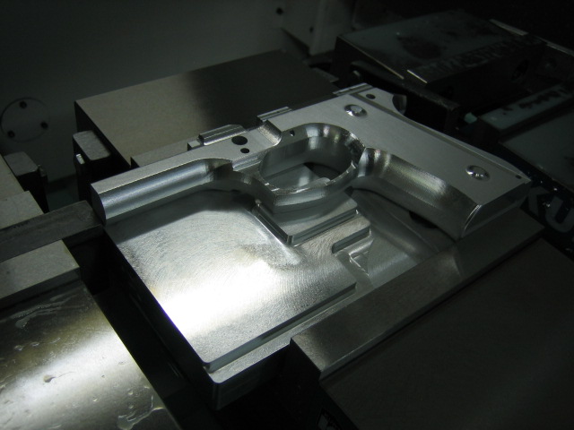
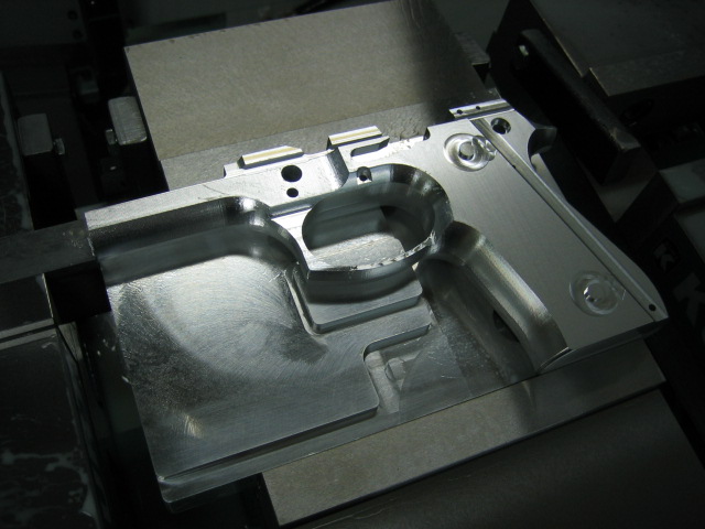
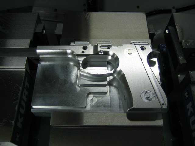
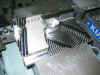
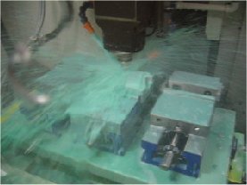
Now
for the fun part, to give the frame some
curves and shapes.. To do this, I
used a 1/4" ball nose carbide end
mill running at 10,000 RPM and 125 IPM
(inches per minute) with a 0.006"
step over. This is the same
process I used for 3-D profiling the 1st
operation. Below are some pics
after this tool ran...
Click
this link
or on the picture below to watch a short
video of the 3-D profiling
process. You can see from the
video that the profiling process can
take a long time. Each time the
tool goes across the frame, it steps
over 0.006" Then machines
back across the frame, and steps over
0.006" again. It keeps
machining back and forth until it
reaches the end of the frame, making a
total of about 1,300 passes. I
looked back at the program to see how
long it was, and for the whole 2nd
operation, the program is 58,976 lines
long!!! Good thing I didn't have
to program each line by hand.
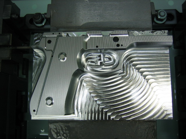
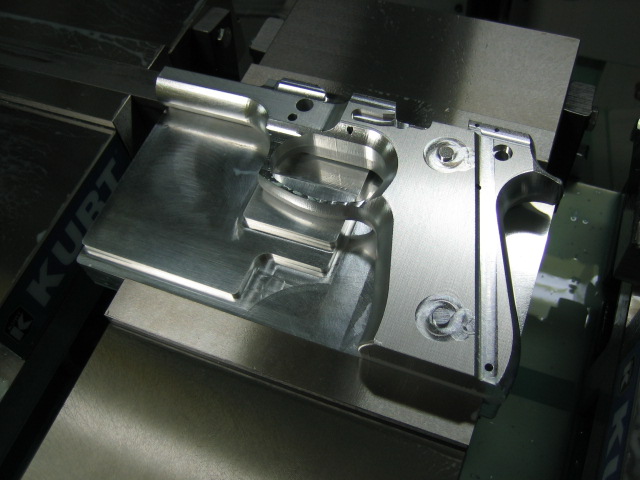
Next
I used a 1/4" carbide end mill to
mill the slot for the slide release and
to contour around the grip screw
bosses. I also contoured the
relief hole for the hammer pin
hole. Here's what it looks like
now...
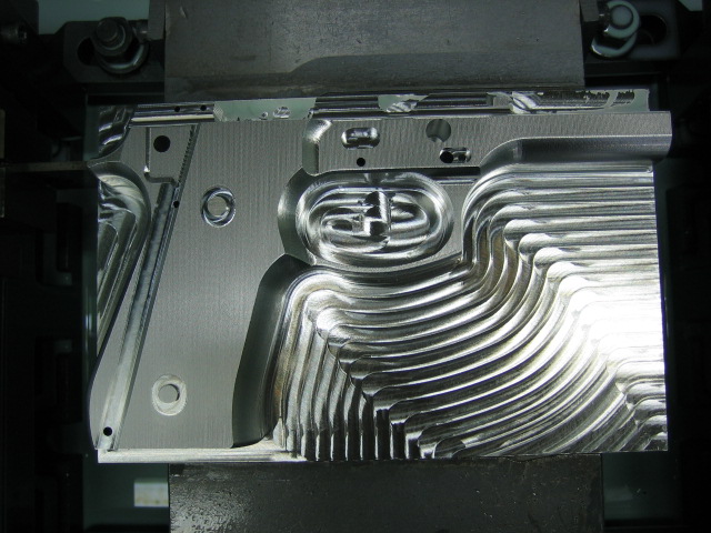
Then
I used a 3/32" carbide end mill to
cut the slide rails and to cut the
relief for the trigger pin hole...
The
last thing to do was to drill the hole
for the slide release lever. Below
are the pics after the 2nd operation was
finished...
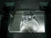
I
bead blasted the frame and took some
better pics to show exactly what has
been done this far. Below are a
couple pics to show how the fixture
plate can support the pistol frame on
both the left and right side...
Here
are a couple close up pics of the
frame...
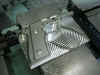
Below
you can see how I am able to slide the
slide on the pistol frame. Of
course I can't slide it all the way back
yet, because the top of the frame hasn't
been machined. My plan for the
next operation is to cut the top of the
frame. Hopefully, this will allow
me to test fit the slide with the barrel
in place.
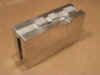
I
got the fixture plates made for the 3rd
operation. I will be able to use
it for the 3rd operation as well as the
operation where I stand the frame on end
to machine down inside the dust
cover. The fixture plates have 2
bosses on each side to align the frame
on the fixture. This will insure
the frame is setting exactly square in
the vise when I start the
machining. Below are a few pics of
what the fixture plates look like...
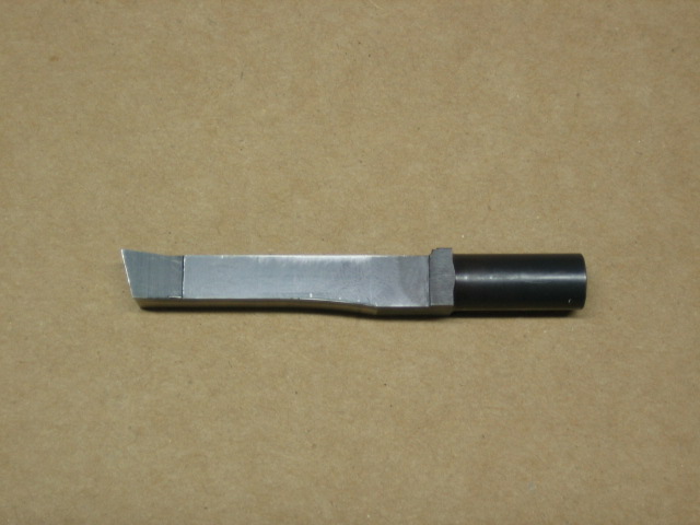
I
got the 3rd operation
machined. For the 3rd operation I
had to do something I've never done
before. I had to make a special
broaching tool and try to broach on the
CNC machining center. I needed to
use a broach to cut the corners square
where the trigger falls in the
frame. Those corners aren't that
big of a deal, since I could just file
them square with a hand file like I've
done in the past with other frames, so
the real reason why I needed the broach
was to cut the ramp inside the frame
where the bottom of the barrel locking
block rides up. Since I was going
to make a broach tool, I wanted to make
sure I could use it in more than one
place. So for this operation I
used it to cut the ramp, and to also cut
the corners where the trigger falls
through. I will also be using it
on one more operation, it'll be the
operation where I make the relief cuts
for the hammer slot. Before you
try to use a broach on a CNC machining
center, you have to make sure the
spindle will lock in position, so there
is zero rotation of the tool in the
machine. Come to find out,
broaching is no easy task on a CNC
machining center. Not only do you
have to make your own special broach,
you have to make a program with a tool
that doesn't necessarily
cut on center. By this I mean,
when you grind the tool, you try your
best to make sure the tool is on center,
but it can be off a little bit because
of how many times you have to flip and
rotate the broach tool on the surface
grinder. And something that didn't
help the situation was the fact that I'm
not a tool & die maker, and I've
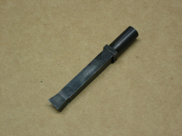
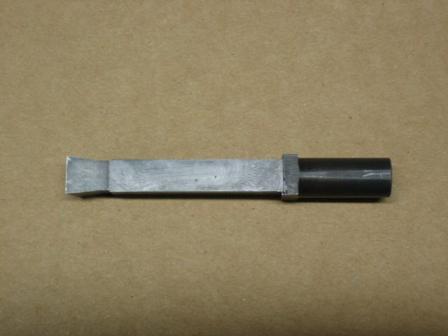
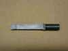
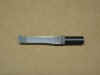
never made a broach tool before. I
started out with a piece of 3/8"
square A2 tool steel blank. I
first set the blank up on the surface
grinder to grind the end round, so I
could have a round shank to hold on to
in the CNC machining center. Then
I set the blank up to grind a 15 degree
angle on the end of the tool, this will
be the main cutting edge. Next I
ground a 7 degree relief cut on the
front and sides of the tool. And
finally I ground the back of the broach
flat so it would have clearance inside
the trigger hole in the frame. I
have no idea if those are the correct
angles for broaching aluminum, but they
looked good when I modeled it up in
Solidworks, and it ended up broaching
perfectly. I left a 0.125"
step where the square part of the broach
meets the round part. I done this
so the tool wouldn't be trying to slide
up inside the holder while I was
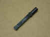
broaching. After I had the broach
made, I wanted to heat treat it so it
would last a long time. Before
heat treat, the steel was something like
a hardness of Rockwell
C30. After I finished heat
treating the broach, it was Rockwell
C62. Below are a few pics of what
the broach tool looked like after it was
finished...
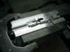
Now
that I had the hard part finished, it
was time to start cutting some
aluminum. I used some 4" tall
steel jaws to help hold the fixture
plates and the frame in the vise.
I also used a c-clamp to hold the top of
the vise tight, since using tall jaws
usually makes the top of the jaws spring
open when you try to clamp on a
part. Below you can see what the
setup looked like at the start of this
operation...
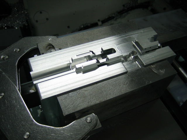
I
first used a 1/4" carbide end mill
to mill out the dust cover area, the
trigger area, the slide release area,
and also the hammer slot in the back of
the frame. Here's what it looked
like after that tool ran...
Next
I used a 1/4" ball nose carbide end
mill to 3-d profile the dust cover and
the rest of the frame...
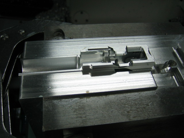
Then
I used a 1/8" carbide end mill to
mill the slot where the hammer release
lever and firing pin catch lever falls
into place. I also used this tool
to clean up the corners down inside the
frame where the trigger will fall
in. This will allow me to only
broach out 1/16" worth of material
instead of 1/8" worth of material
that was left behind by the 1/4"
end mill. Here's what it looked
like after those areas were cut...
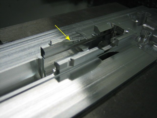
I
also used the 1/8" carbide end mill
to mill two ramps on each side of the
frame. In the pic below you can
see the arrow pointing to the area that
was cut. After the 1/8" end
mill, I used a 5/16" x 0.060"
woodruff cutter to cut the undercut for
where the lugs on the barrel locking
block slides into the frame...
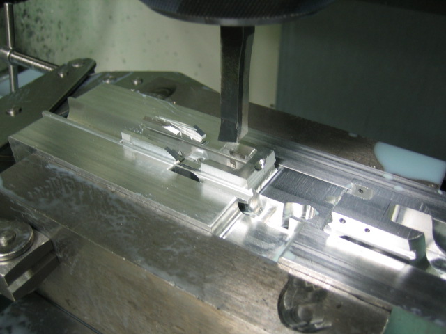
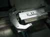
Now
it was time for the fun part. It
was time to see if my broach tool would
work. After I had the broach in a
tool holder, I had to make sure it was
square with the machine. To do
this, I locked the spindle in position
so the tool wouldn't turn.
Then I took the tool down to right in
front of the vise jaw. At this
point the spindle was locked, and I had
the broach loose in the tool holder so I
could turn it. I kept stepping the
tool forward and wiggling the broach
until the broach was within about a thousandth
of the vise jaw. Then I tightened
the broach in the tool holder. So
now the broach was exactly square with
the vise jaw which meant it was square
with the machine. When I
programmed the broaching tool path on
the computer, I programmed it from the
corner of the tool. It would be
hard to find the exact center of the
broach compared to the tool holder, so
it was easier to just program it from
the corner. To find the
corner, I jogged the machine to the
front and then the side of the vise
jaw. I knew where the exact corner
was of the vise jaw, so after I touched
off on the front and the side of the
broach on these surfaces, I could then
calculate the where the corner of the
tool was in relation to the tool holder
center. Getting all of this setup
was a lot of work, so after this
operation I left the broach in the tool
holder so I could use it on the
operation where I'll be broaching the
area for the hammer slot. I
broached the left side of the trigger
hole and the barrel locking block ramp,
then I told the machine to rotate the
tool 180 degrees and lock the spindle in
again so I could broach the right side
of the trigger hole. To broach the
trigger hole, the broach only had to
make a up and down movement. But
to broach the angle, I had to not only
program the broach where it would go up
and down, I had to also program it where
the broach would come down as it was
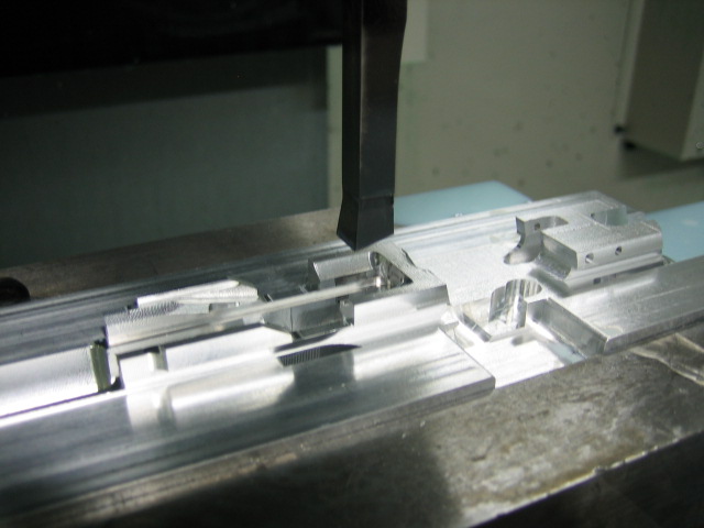
also moving left to right. Below
are a couple pics of what the broach
looked like before it started
broaching. In these pics, the
broach is set to cut the left side of
the trigger hole and the ramp...

I
shot a short video to show the exact
movements the broach was taking as it
was cutting the barrel locking
ramp. Click on this link
or on the picture below to view the
video...
The
broach tool ended up working
perfectly. I was really happy with
the results of the first time I tried to
make a broaching tool and broaching on a
CNC machining center.
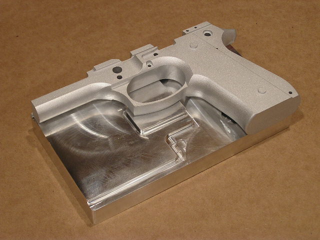
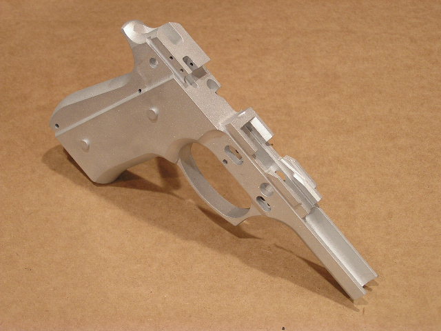
I
took some better pics to show what the
frame now looks like. I also took
a couple close up shots to show exactly what
this operation done...

I
was excited to see how the slide and
barrel fit in the frame, so I got some
parts together and tested it out.
Below you can see what it looks like...
So
far everything is fitting
perfectly. I can't wait to get
this thing finished and take it out for
the first test shots. That's it
for the 3rd operation. The next
operation I'll be standing the frame on
end, and machining down inside the dust
cover so the guide rod and spring can
slide in.
Continued
on page 2...
Page
1 Page
2