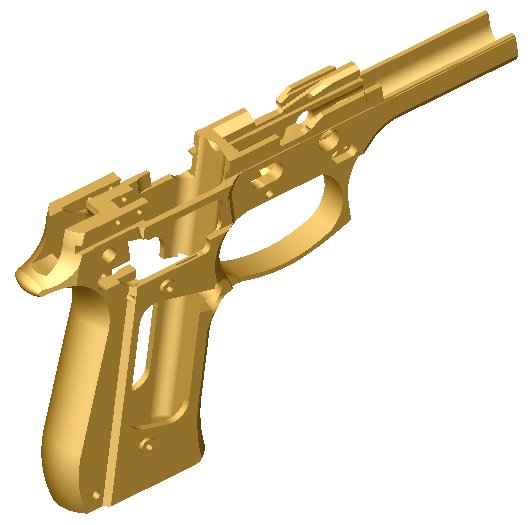
Beretta 92FS/M9 Frame
Page
1 Page 2

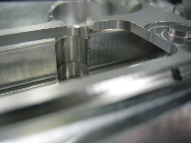
For
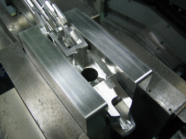
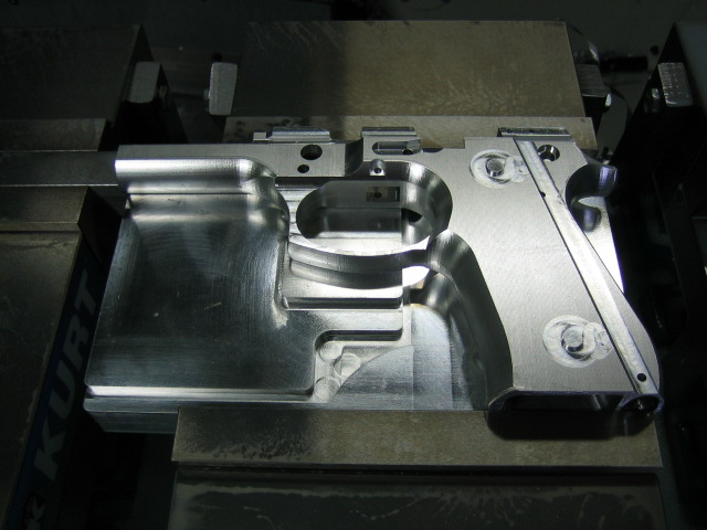
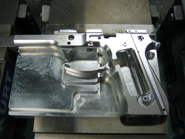
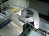
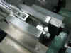
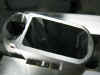
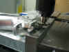
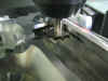
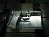
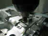
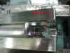
the 4th operation I stood the
frame on end, and machined down inside
the dust cover. This operation
removed the radius left behind from the
ball nose end mill when the dust cover
was machined on the 3rd operation.
The 4th operation also machined the hole
for the guide rod. Here is what
the setup looked like...
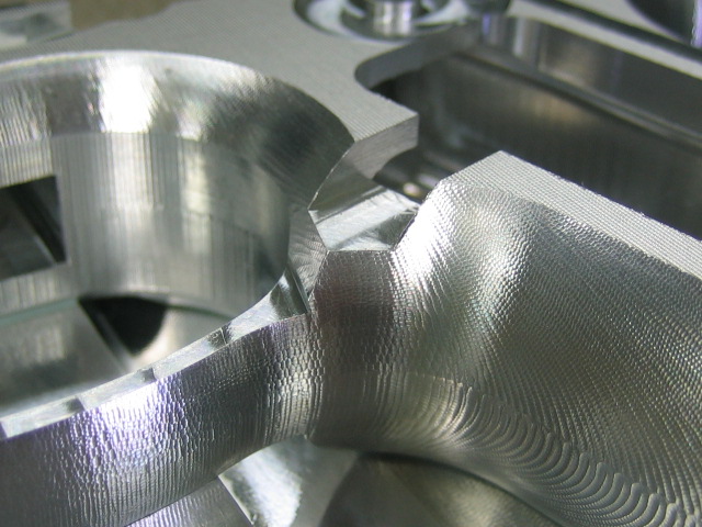
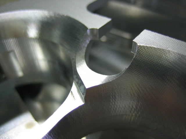
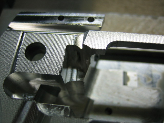
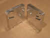
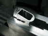
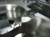
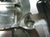
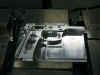
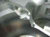
In
this next picture you can see the radius
that the ball nose end mill left.
You can also see how on the 3rd
operation I roughed out the area where
the guide rod will slide in...
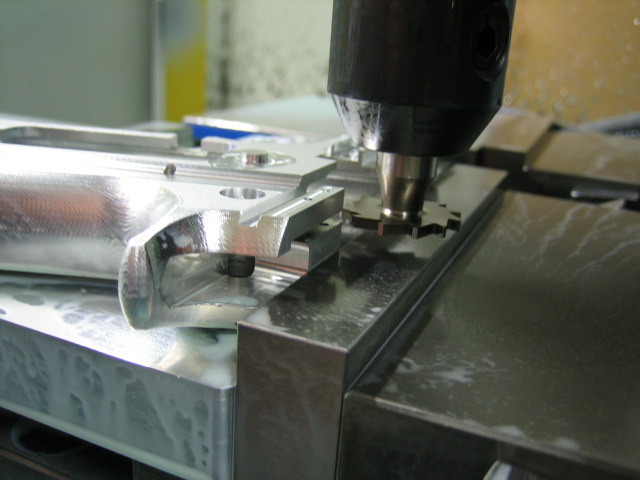
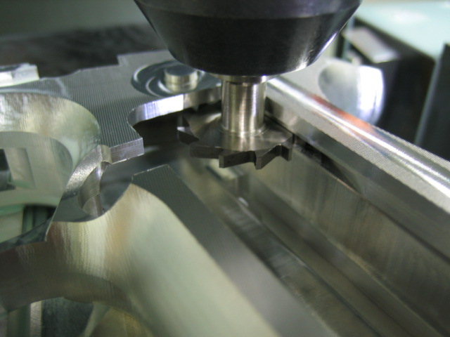
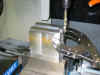
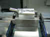
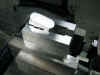
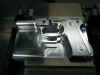
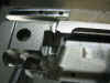
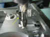
The
only tool I used on this operation was a
4" long 3/8" carbide end
mill. This end mill has been
pretty handy. It's the same tool I
used for the AR15 upper receivers and a
coupe other frames. Here's a pic
as it was machining the dust cover
area...
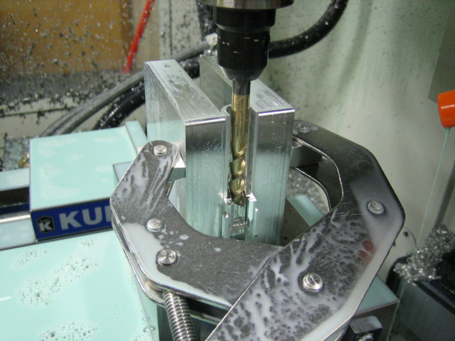
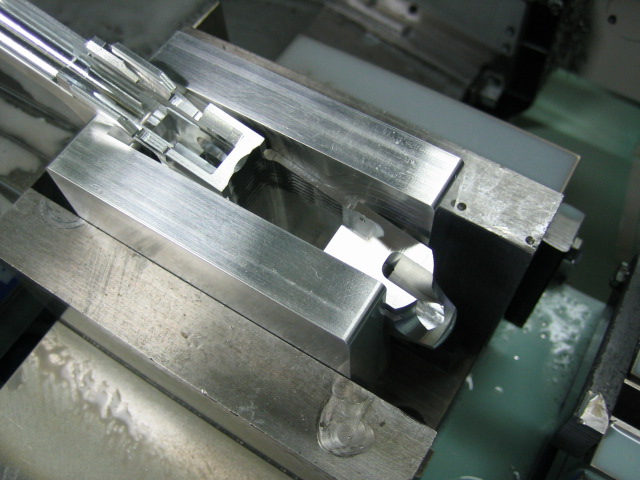
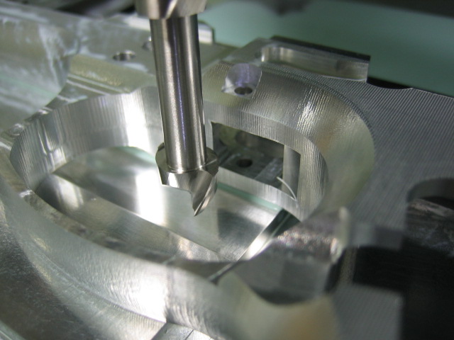
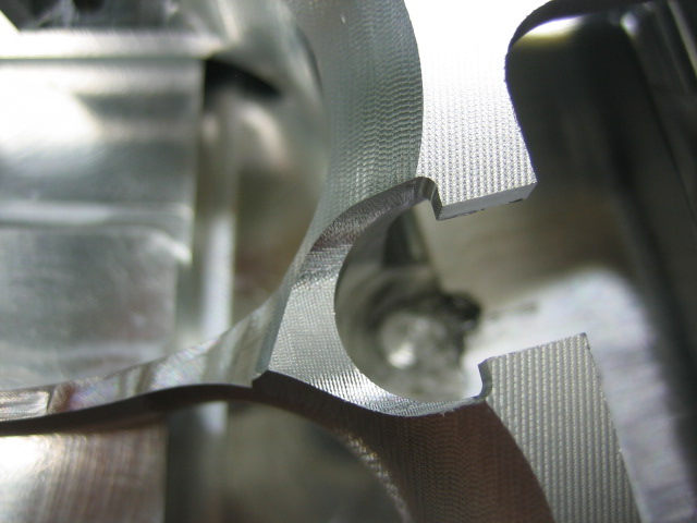
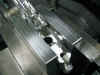
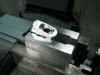
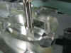
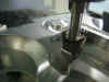
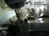
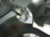
And
here's where it was starting to cut the
guide rod hole...

BTW,
I used the big C-clamp to make sure the
frame didn't vibrate while it was being
machined. I use this C-clamp
whenever my part sticks above the jaws
any great distance.
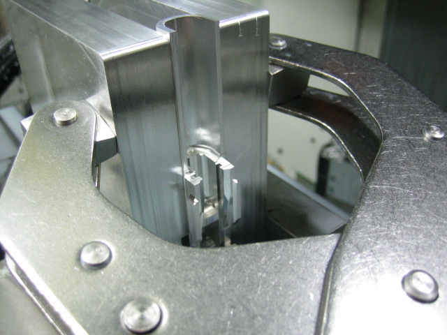
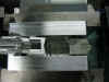
On
the 5th operation I machined the
top of the mag well. I machined
the mag well in two steps, first the top
half and then the bottom half. It
would have been nice to use a wire EDM
machine to cut out this material, but
since I don't have access to a wire
machine I had to machine the material
out. You might be able to machine
the whole mag well at one time, but that
would take some really long end mills,
and really long end mills tend to
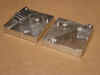
vibrate very easily. I had to make
a couple new fixture plates to hold the
frame. These new fixture plates
allow the frame to be held with the mag
well being exactly vertical. I
designed the plates so they could be
used on this operation and also when I
machine the bottom part of the mag
well. Here is what the plates look
like...
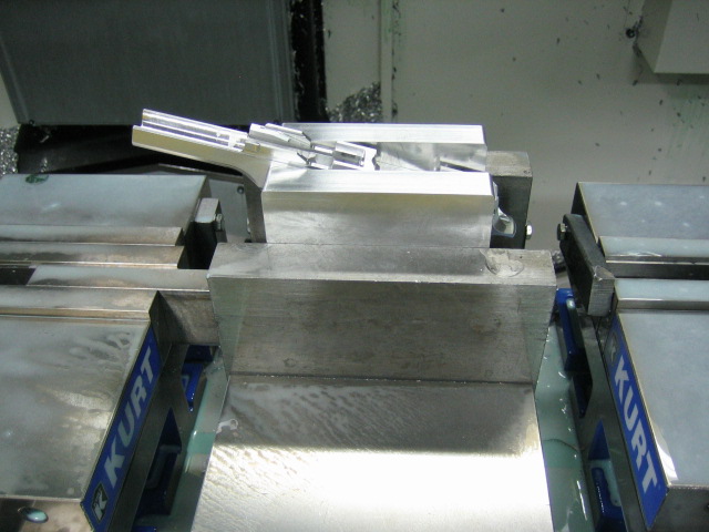
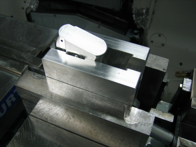
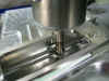
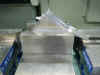
Here
is what the frame looks like on the
fixture plates and ready to be
machined...
I
wanted to have a hole for my long end
mills to drop down in when they machined
the mag well, so I used a 37/64
drill to drill the hole. Drills
don't like drilling on angled surfaces,
so I had to machine a flat spot for the
drill to start. In this next pic
you can see how I machined down into the
mag well a little bit and then drilled
the hole on the flat surface.
Having this hole will make it easier on
the long end mills and keep them from
vibrating as much...
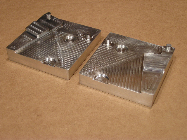
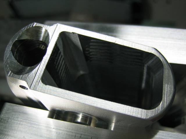
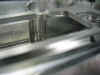
I
used a long 1/2 hog end mill to rough
out the pocket and then came back with
the long 3/8 carbide end mill. I
also used a 1/4 and 1/8 end mills to
clean up the corners on the back side of
the mag well. This will allow me
to use a hand file to file out a
0.0625" radius instead of a
0.1875" radius left behind by the
3/8 end mill. Here's a couple pics
after this operation was finished...
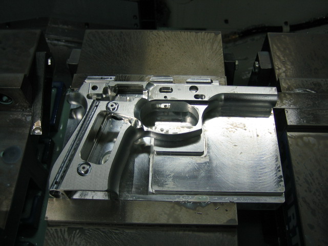
The
6th operation I machined the
bottom half of the mag well and done a
little 3-d profiling on a couple
surfaces. Here you can see what it
looked like at the start of this
operation...
I
done the same thing with the bottom as
the top, I milled a flat spot for the
drill to start, drilled the hole and
then milled the pocket...
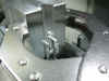
In
this pic you can see that the mag well
is finished, and I've milled a flat spot
for the main spring housing drill to
start...
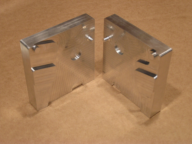
And
here is what the frame looked like at
the end of this operation. You can
see that the main spring housing hole is
drilled, and I've used a 1/4 ball nose
end mill to 3-d machine the area around
the hole and also the relief on the mag
well...
For
the 7th operation I done some
detail work on the left side of the
frame. I saved this detail work
until now, because now I will only be
removing a little bit of material in
some spots since a lot of the frame has
now been machined away. This
operation had a total of 5 undercut
tools. I had to make one new 7/16
undercut tool. Two of the undercut
tools I had from the 1911 project.
And I had to order two new woodruff
undercut tools. Here is what the
start of this operation looked like...
I
first used a 1/4 carbide end mill to
mill out the pocket so I could access
the inside of the frame...

A
really detailed area on this operation
was the mag release area. Here is
a close up of that area after the 1/4
end mill ran...

I
then used a 1/8 ball nose end mill to
3-d profile the mag release area...
Next
I used a 1/2 undercut tool to machine
the little area under the trigger
hole...
Then
was the 1" woodruff cutter.
This cutter machined the slot where the
ejector will set in...
Next
up was the 9/16 undercut tool.
With this tool I machined the area on
the back side of the mag well. So
now I won't have to use a hand file to
file out the corners in the middle of
the mag well. I will only have to
use the file on the ends of the mag
well...
Now
it was time to machine the area for the
mag release. I needed a 7/16
undercut tool. This is the tool I
had to make. I normally make my
undercut tools from flat bottom end
mills, but the only thing I could find
at the shop was a ball nose end
mill. So I decided to grind the
ball nose off the end, and then grind
the undercut on the tool. Come to
find out, this tool worked
perfectly. I also took a close up
of the area that it cut...
And
this is how the 7/16 undercut tool left
the mag release area...

Here
is the 7/8 woodruff cutter machining the
undercut for the sear spring...
I
then went back with a 1/16 ball nose end
mill to clean up the corners on the mag
release area. This almost made the
corners square. Now I will only
have to file out a little piece of
material in order for the mag release to
slide in...
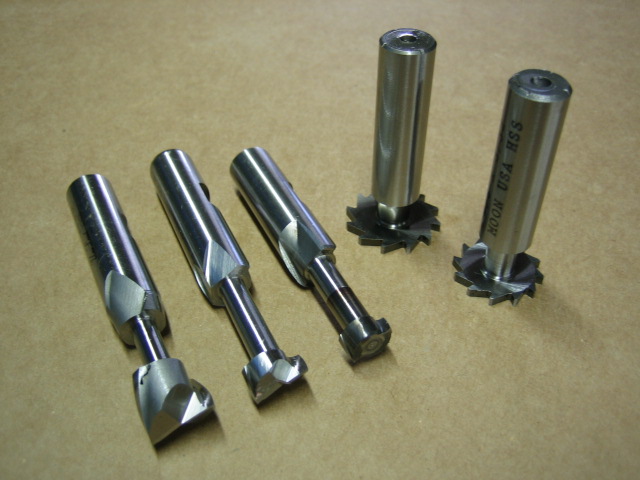
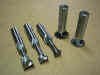
Finally,
I drilled the holes for the grip
screws. I didn't drill these holes
on the 2nd operation because at the time
I wasn't sure what size thread it
was. But now I know it's a
M3x0.5 That is the size of thread
for the screw. On the actual
Beretta frame, they use a grip bushing,
so the hole in the frame is
bigger. I won't be installing
bushings on my frame, since my bushings
are already built in...
Here
is a pic of the different undercut tools
I used on this operation...
That's
it for the 7th operation. On the
8th operation I'll be doing basically
the same thing to the right side of the
frame. It'll have a couple
different cuts, but I don't see any
major problems. So this weekend, I
had some really good luck. On
Friday, I only had the 3rd operation
finished, and now I'm up to the 8th
operation. Hopefully I'll have the
same luck next weekend. I think I
should be able to have the frame
complete in a couple more days of
work.
For
the 8th operation, I machined the
detail work on the right side of the
frame. Here is what the setup
looked like...
I
used a 1/4" carbide end mill to
machine out the big slot in the pistol
grip. I also used this tool to
machine the big cut out for where the
trigger bar slides through. This
is what it looked like after this tool
ran...
Then
I used a 1/8" and 1/16"
carbide end mills to clean out the
corner for where the firing pin catch
lever slides in...
Next
I cut the clearance for the
hammer. I made this cut with a
1.500" x 1/4" woodruff
cutter. Here is what it looked
like when this tool ran...
I
then used a 1/2" x 1/32"
woodruff cutter to cut the slot for
where the trigger bar spring sets in...
I
had to make a special 5/16"
undercut tool for the next cut.
This cut was a clearance cut for the
sear. The cut is basically just a
slot, but you have to use a undercut
tool otherwise the sear won't have the
proper clearance.
The
final tools to run was the 1/8" and
1/16" ball nose carbide end
mills. These two tools made the
same 3-d cuts as on the 7th operation,
which were the cuts for the mag
catch. Here's a before and after
shot...
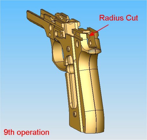
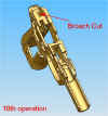
For
the 9th operation and 10th
operation, I continued to make
clearance cuts for the hammer. The
9th operation machined the radius down
inside the frame for the hammer
clearance. And the 10th operation
broached the square corners inside the
frame. Here are a couple sketches
to show exactly what the cuts are...

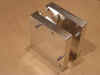
In
order to hold the frame for these
complicated cuts, I used the fixture I
made for the 5th & 6th operations,
which was when I machined the mag
well. In order to hold the frame
at the correct angle, I drilled 4 new
holes in the back of the fixture.
Two of the holes were used on the 9th
operation and the other two for the 10th
operation. I made the holes where
I could slide in a couple dowel
pins. After the two dowel pins
were inserted into the fixture, I set
the fixture inside the 4" tall jaws
and let the two dowel pins rest on top
of the 4" jaws. In order to
get the proper angle for the 10th
operation, I simply remove the dowel
pins and insert them into the other two
holes. Here is a sketch showing
how the dowel pins make the frame set at
a different angle...

Here
is a pic showing the new holes in the
back of the fixture...
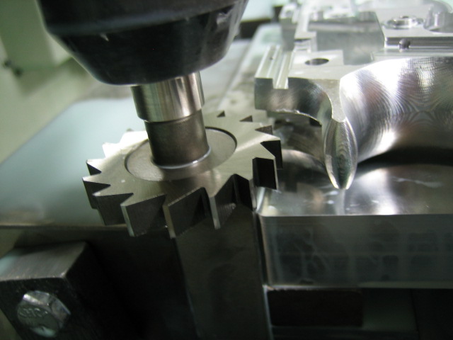
This
is what the fixture and frame looked
like in the 9th operation...
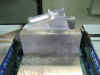
Here
you can see how the dowel pins set on
top of the jaws...
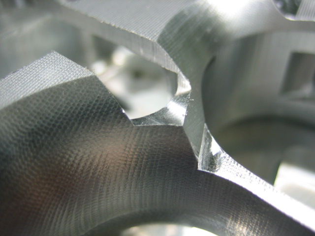
And
here is the radius that the 1/4"
long carbide end mill cut on the 9th
operation...
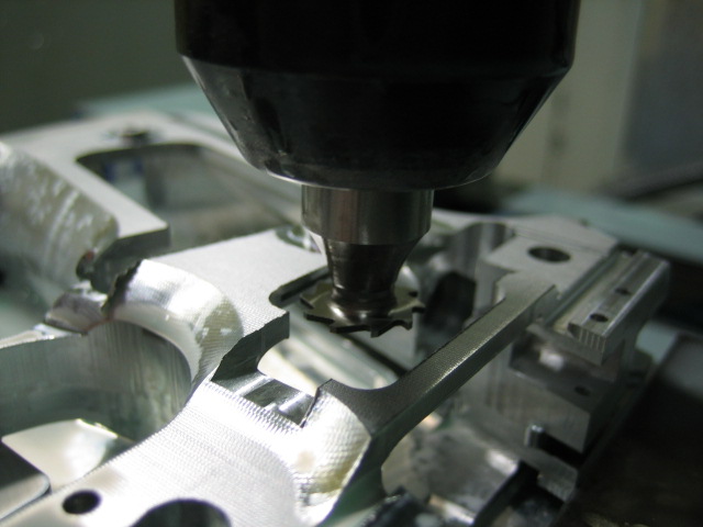
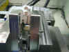
For
the 10th operation, I used the special
broach I made for the 3rd
operation. Back when I made the
broaching tool, I made sure I could use
it on all the broaching
operations. This operation used
the 1/4" long carbide end mill and
then finished out the corners with the
broaching tool. This is a pic of
what the 10th operation setup looked
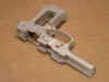
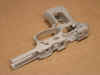
like...
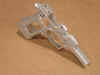
The
machining of the 10th operation is now
finished. This chunk of aluminum
has come a long way. It started
out as a 5.7 pound block of aluminum,
but it's now a 0.4 pound pistol
frame. I bead blasted the frame
and took some good pics of what the
frame looks like...
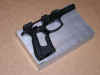

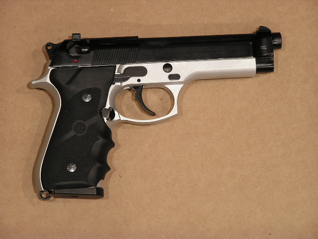
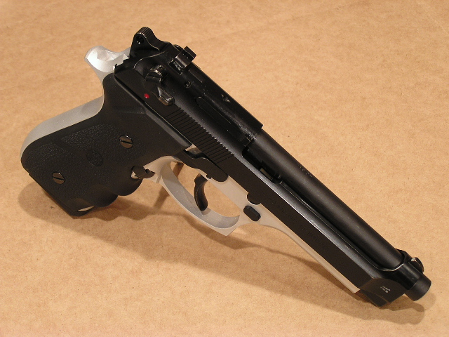
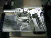
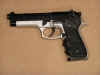
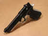
I
done a little tweaking on the frame with
a small hand file, but other than that
all the parts fell right into
place. Here is what the completed
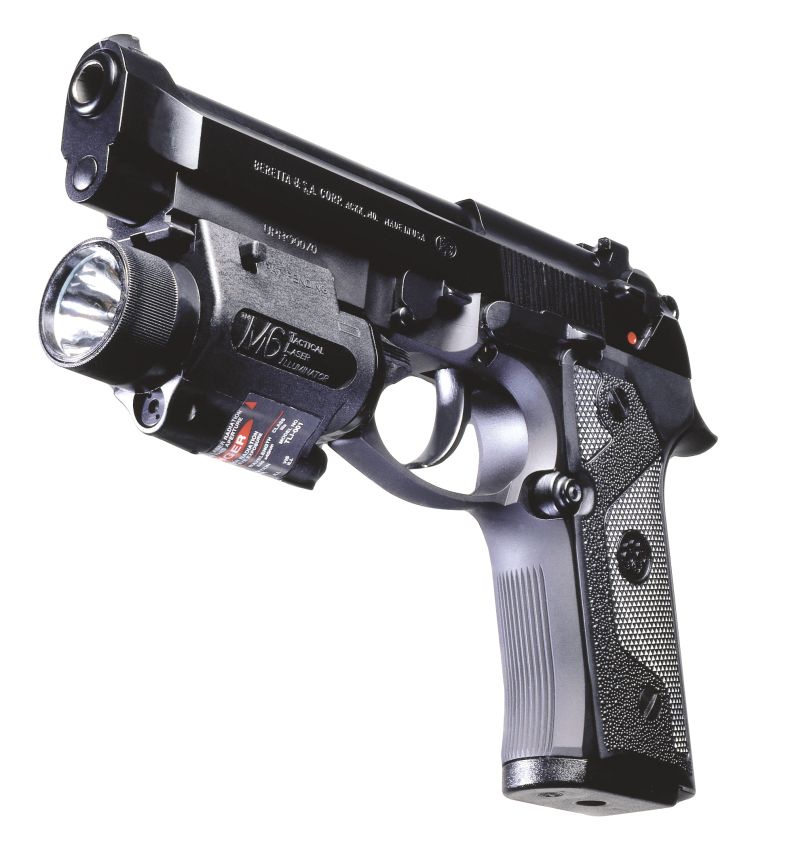
pistol looks like...

After
I had the pistol put together, I double
and triple checked everything to make
sure everything was working
correctly. I then grabbed a box of
shells and took it out for her first
shots. I was very happy with the
results. I shot a 50 round box of
shells, and I didn't have one problem
what so ever. I didn't want to
shot any more than a box of shells,
because the frame is still bare
aluminum. I'm going to now strip
the pistol back down to the bare frame
and black anodize it. I'll upload
some final pics when I get the pistol completely
finished. If you don't count my
time and the material cost of the frame
I made, this Beretta 92FS pistol cost me
$169.95 The parts kit was $19.95,
and the barrel/slide assembly was
$149.95 Not a bad deal for a
Beretta 92FS huh?
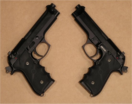
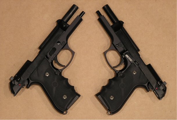
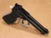
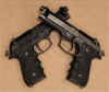
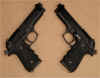
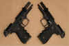
I
finally found time to black anodize the
frame. I completed two of the
frames, so now I have matching dualies.
I switched the left handed pistol so the
mag release is on the right side.
This way I can hold a pistol in each
hand and just use my thumbs to drop the
mags. Below are a few pics of the
finished pistols...
This
was by far the hardest project I've done
so far. It had alot of little
undercuts, and it also needed to be
broached in a few areas. The good
thing about hard projects, is that you
learn more and it's more
interesting.
Page
1 Page 2