AR-15 A2 Upper Receiver
After I finished the AR-15 lower receivers I didn't want to buy all the upper receivers to complete the rifles, so I decided to give machining the upper receivers a try. I got my hands on the upper receiver solid model (the CAD file), but the model was for the A3 upper receiver. I was wanting to machine the A2 upper since it would be more of a challenge because there were less flat surfaces to hold on to compared to the A3. I pretty much knew if I could machine the A2 upper, I could also machine the A3. I spent several days converting the A3 solid model into an A2 solid model. It seems easy enough, all it needs is just a handle right? Well I found out that adding that little handle took a whole lot of work. I like for my stuff to be perfect, so I took my time and made sure everything was correct. After I had the A2 upper receiver solid model complete I went back to double and triple check everything that I had done. This way I knew the solid model was good instead of getting half way through the project and finding out that I had made a stupid mistake. There are companies that sell the upper receiver forgings, and like the lower receiver forgings it's just a block of material that looks like the receiver. And once again, for more of a challenge, I decided to machine my uppers from just a billet of aluminum. I think the hardest part of starting the upper receivers is getting the 1" hole all the way through the receiver. There are so many different surfaces on the upper receiver that it would be very difficult for me machine the whole receiver and then drill the 1" hole. So I went with drilling the 1" hole first, since it would be very easy to locate the block of material in the machine. After the 1" hole was drilled, I had to make sure I located every operation thereafter off this hole, otherwise the hole location might end up being way off compared to the receiver. To drill the hole I bought a super long drill bit, so I could drill all the way through the receiver at one time. The problem in drilling deep holes is that the drill bit will tend to walk off position if the chips build up in the hole. So to cure this problem, I took really small pecks with the drill. Pecks of around 0.050" each time. So as you can imagine this took a really long time to drill all the way through the receiver, but the good thing is, the drill didn't walk off.
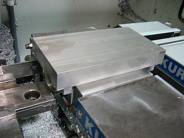
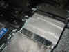
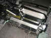
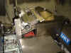
Here is what the blocks looked like after the 1" hole was drilled through...

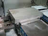
This is a pic at the start of the 1st operation. In this pic you can see how I machined the basic profile of the receiver...

Here is what the receiver looked like after the 1st operation. I done the same basic profiling operations as on the lower receiver. I first used a 1/2" carbide ball nose endmill, and then made a finish pass using a 1/4" carbide ball nose endmill...
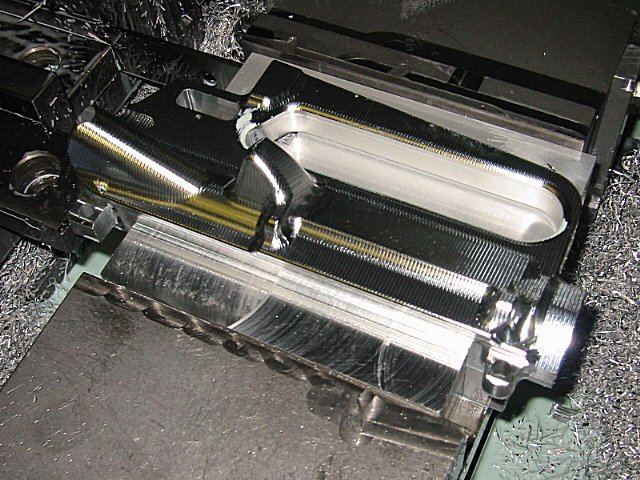
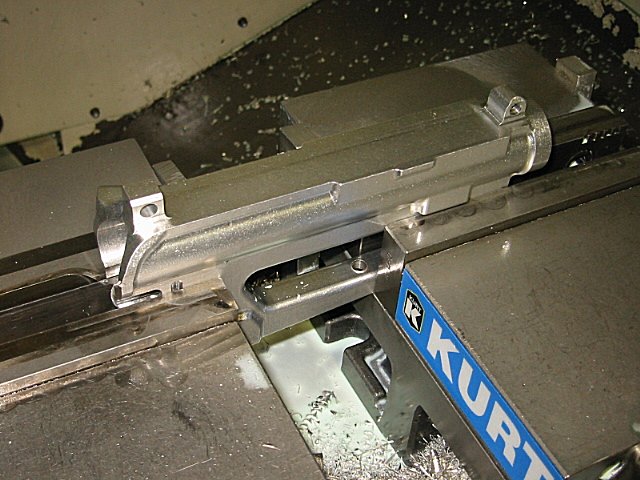
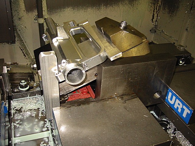
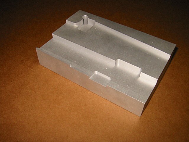
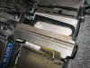
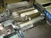
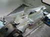
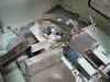
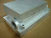
For the 2nd operation, I had to make a special fixture so the receiver could set flat and square in the vice. In this picture you can see the fixture that I designed...
You can see in this pic that the receiver is setting flat in the vice and ready to be machined...
To remove most of the material around the handle, I used a 3" shell mill to machine down to almost the exact thickness of the handle...
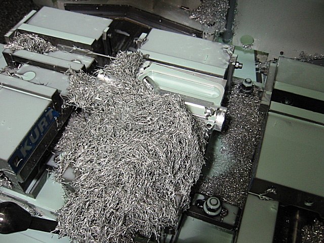
The next tool to run was the 1/2" carbide ball nose endmill to rough the profile. During this step, this tool removed a whole lot of material. Can you see the receiver under all the chips?...
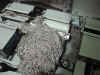
Here is a better pic after all the chips were brushed away. You can see how the profile is still rough from the 1/2" endmill...
And here is the receiver after the 1/4" carbide ball nose endmill made the finish profiling pass...
To get a good idea of the work I've done this far, here is a pic of the upper receiver and the finish lower receiver...
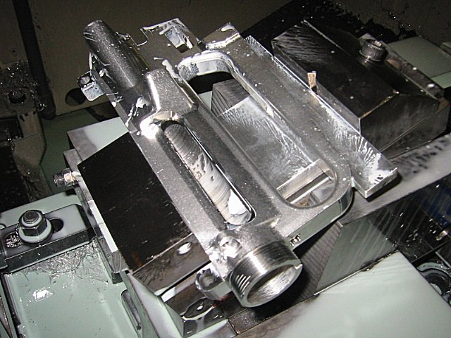
For the 3rd operation I machined the top of the receiver. I clamped the receiver in the vice using the 2 ears on the bottom of the receiver. Here you can see the setup that I used...
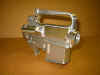
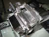
This is a picture after the 3rd operation was finished...
The 4th operation I machined the bottom of the receiver. I know the setup I used on this operation (clamping using 2 vices) probably isn't the best possible way, but I thought it was the easiest since the handle has those tabs that stick out the side of the receiver. I probably could have made a fixture to clamp on both sides of the receiver, but I thought this would be a quick and dirty way of doing it...

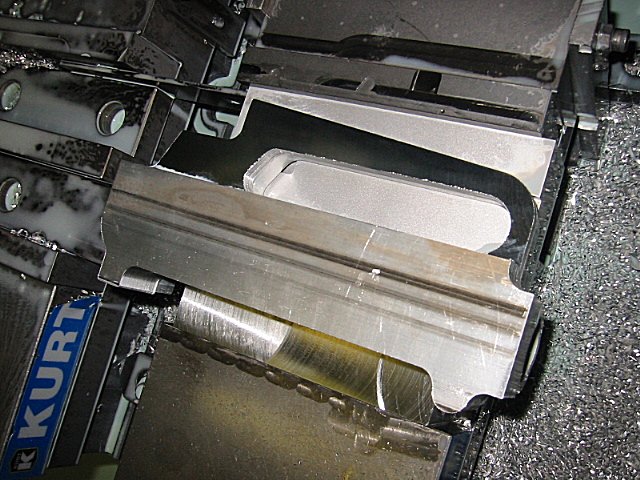
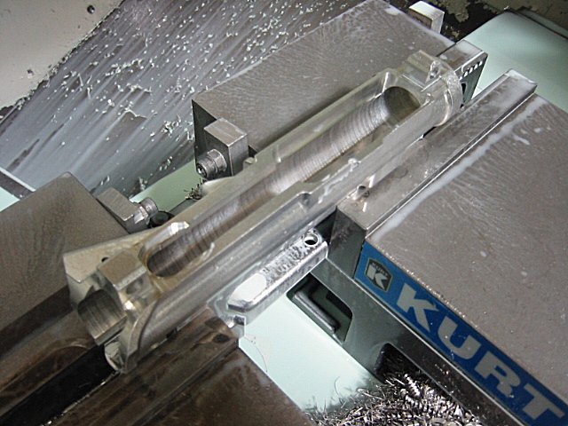
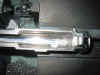
And here's a pic after the 4th operation was finished. I had to use a super long endmill to machine that groove that runs down in the bottom of the receiver...

Here's a closer look at the groove down in the bottom of the receiver...
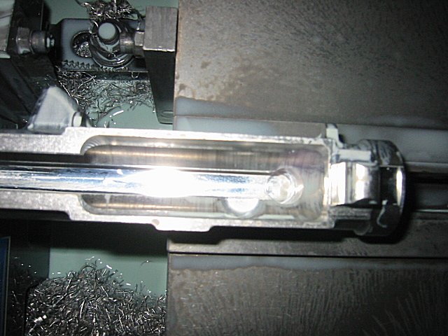
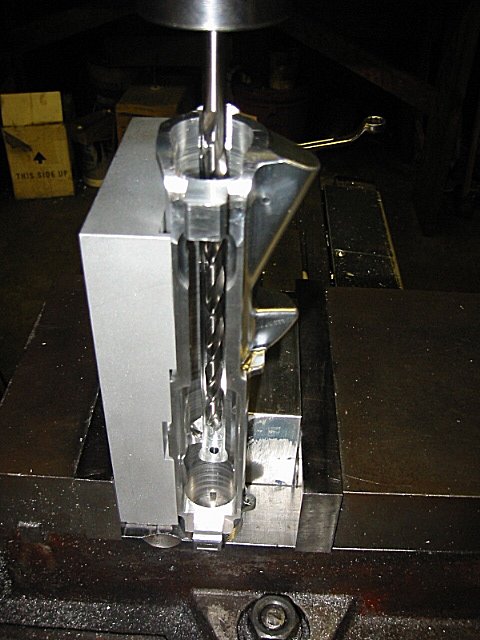
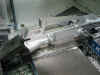
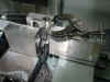
The 5th operation had another weird setup, but hey it worked. This operation would machine the threads on the end of the receiver. The hard part about doing this operation was making sure the receiver was very secure in the vice, and making sure that there wouldn't be any vibrations...
This is a pic after the 5th operation was finished. I cut the threads using the same thread mill that I used on the lower receiver...
Machining the upper receiver is no easy task as you can tell from the setups. Here is what the 6th operation setup looked like. This operation machined the ejection port...
And here is what the receiver looks like after the 6th operation...
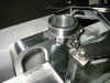
For the 7th operation I drilled the hole that's down inside the receiver. This hole is for clearance when you install the gas tube. If you didn't have this hole, I don't believe you could install the gas tube correctly...

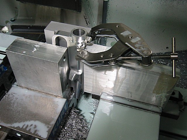
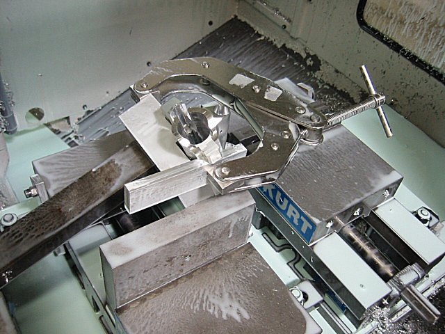
The 8th operation was the last weird setup that I had to deal with. And I think this was about the craziest that I done so far. But once again, it worked. This last operation done the forward assist hole...
The only thing left was to drill the holes for the dust cover pin. I done this on the manual mill, and I tried so many different things that once I found something that would work, I forgot to take a picture of it. Sorry about that. But I'm sure if you are able to machine a receiver to this point, that you can figure out a way of holding the receiver to drill these two holes. After I had these two holes drilled, the A2 upper receiver was finished. The next project would be the A3 upper receiver.
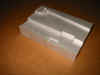
Here is a good picture of the setup block that I had to make to help hold the receiver...
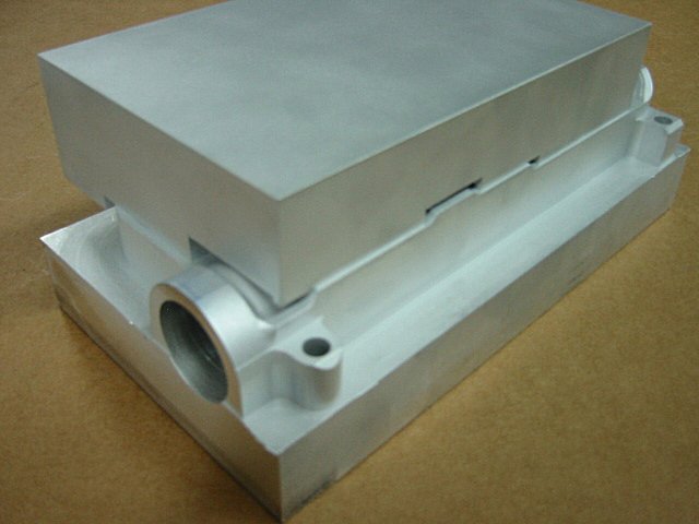
And here is what it looked like after the fixture was set on top of the receiver after the 1st operation. You can see that I tried to use as many contact surfaces as possible...
I hope you enjoyed this project.