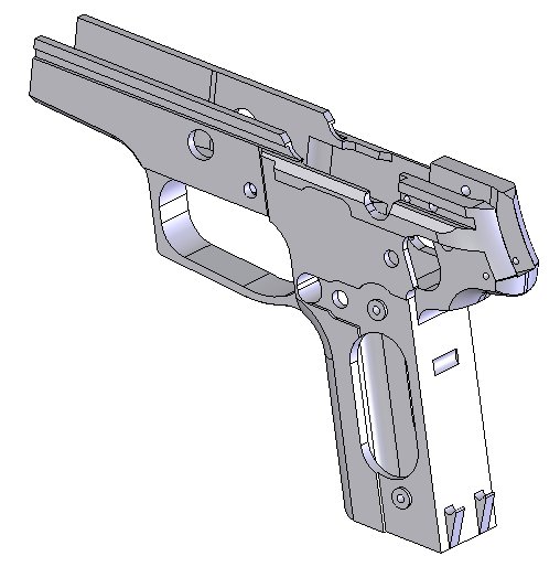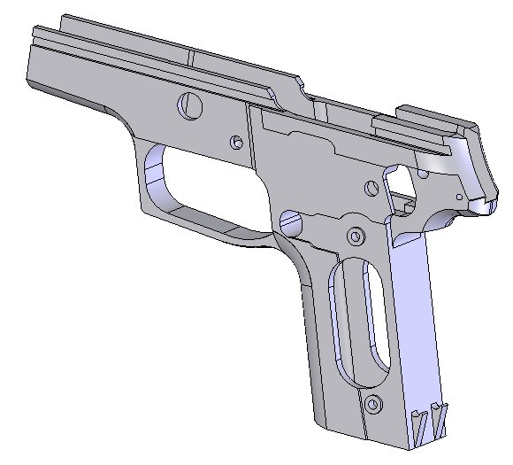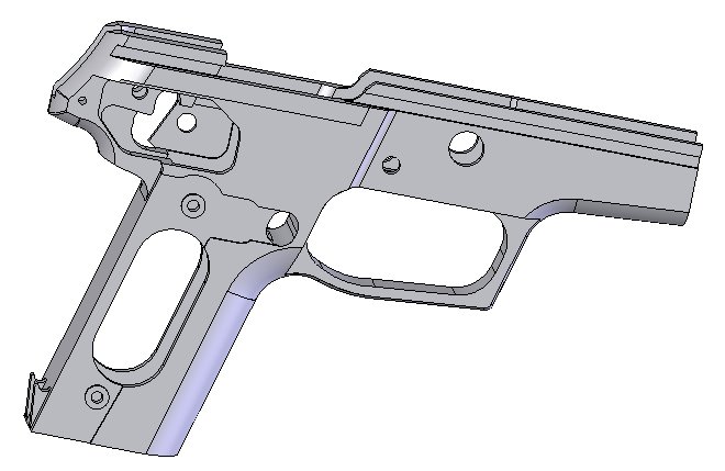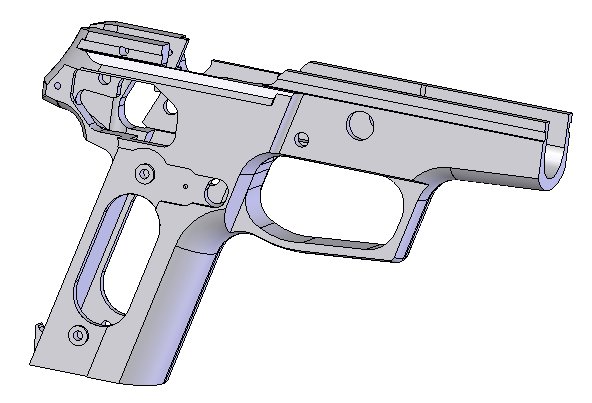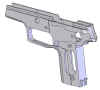
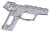
I've done some more work on the P228 solid model. I still have a little more work to do, and then I'll be ready to double check my work to insure everything is correct. I hope to start the machining in 3-4 weeks. I've uploaded a couple new pics of the work I've done lately...
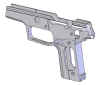
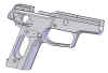
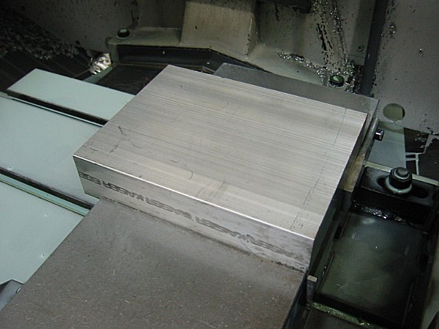
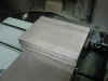
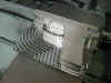
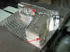
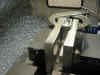
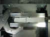
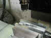
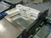
I now have the P228 solid model nearly complete. I still have a few minor features to add to the model, and I will add new solid model pics once the model is 100% complete. Since there are only minor things left on the model, I was able to start the machining. I spent a full day just programming the 1st operation. This 1st operation ended up having 16 tools. After I finally got the program finished, I cut the stock for the frame and got the CNC setup to start the 1st operation. The stock I ended up using was 5 x 1.500 x 6.68 6061T6 aluminum. I probably could have used a smaller size, but that was the closest thing I could find without ordering special material. Here is a pic at the start of the 1st operation...
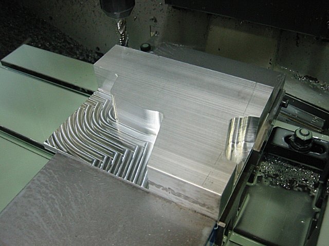
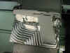
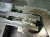
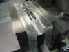
This is a pic I took as the 1/2 hog endmill was roughing the profile. You can see that it is starting to take shape...
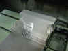
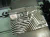
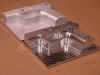
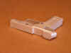
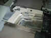
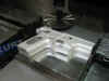
And here is what it looked like after the 1/2 hog endmill was finished cutting...
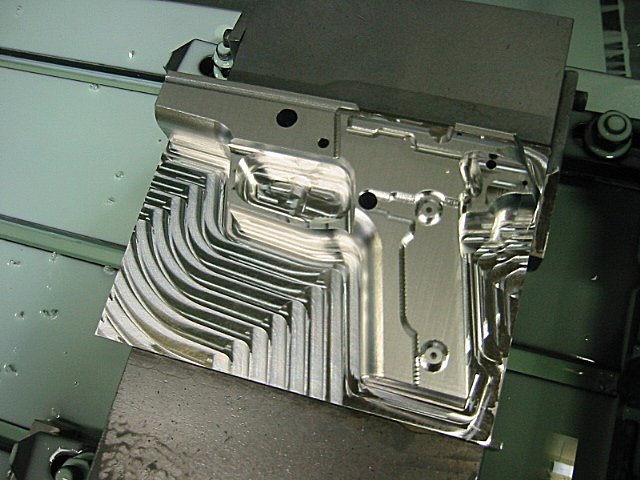
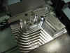
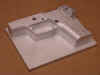
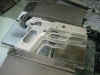
This is a pic after the 1/4 carbide endmill made some clean up passes and milled some detailed areas...
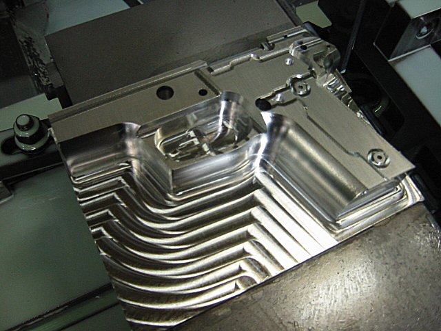
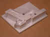
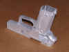
I then used a 1/4 ball nose carbide endmill to 3-D profile the whole frame. I decided it would be easier to do this rather than trying to program all the curved surfaces and different step heights that the P228 has. Profiling the whole frame probably took a little longer to machine, but it gave the frame a nice even finish and I didn't have to worry about blending different tools in. Here is what it looked like after the profiling was finished...
I then started drilling all the holes. Come to find out, nearly every single hole on the frame is a different size. I was only able to use the same drill for 2 holes. Here is a pic after all the holes were drilled...

I then used some smaller endmills to machine some detailed areas and to cut the rails. This is a pic after all this was finished...
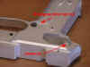
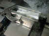
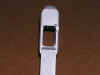
I then used a 1.5 x .375 woodruff cutter to mill the undercut area for the main spring seat. I had to make a special undercut tool (1/4 x 0.100) to mill the undercut inside the mag catch release hole. This undercut is what keeps the mag catch from coming out. The side of the mag catch has a detent, and this detent catches on the undercut. This is a bad picture, but maybe you can see the areas I'm talking about. You will be able to see these areas better in later pics...
I bead blasted one of the frames and took some good pics with a better digital camera. Here is how the frames compare...one is bead blasted and one is straight off the machine...
The next few pics are some better close up shots...
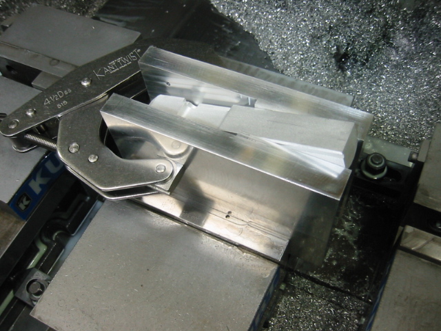
That is the end of the 1st operation. I will have to design a special fixture/jig to hold the frame for the 2nd operation. I'm going to try and get this fixture made this week, so I can start the 2nd operation next weekend. For the 2nd operation, I will be machining the right side of the frame. And for the 3rd operation, I'm thinking of machining the magazine well, since that area will still be solid and I won't have to worry about a drill "walking" off position. Then for the 4th operation, I'll be machining the top of the frame. There may have to be a 5th operation, but I'm not sure yet, it just depends on how much I can get machined on the 2nd operation.
I
got the fixture made for the 2nd
operation. I kept the design
as simple as possible, because the 2nd
operation programming was going to be
almost as complicated as the 1st
operation. This fixture will allow
the frame to set flat and square in the
vice while I complete the this
operation. Here is a pic of the
fixture and the setup that I used...
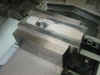
Here
is a pic at the start of the 2nd
operation...
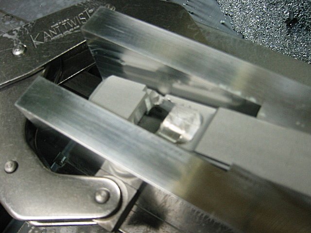
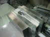
I
used a 1/2" hog endmill to contour
around the outside of the frame so most
of the excess material could be removed
before I started flycutting the frame...
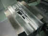
I
then used a 3" shell mill to flycut
the frame down to the correct
thickness...
After
the frame was milled to the correct
thickness, I came back with the
1/2" hog endmill and roughed some
more of the material out...
Then
I used a 1/4" carbide endmill to
make some finish cuts on the frame...
It
was now time to 3-d profile the
frame. As usual I used a 1/4"
carbide ball nose endmill to profile
across the whole frame. This is
what the frame looked like once the
profile was finished...
I
used some smaller endmills to make some
clean up cuts around the pistol grip and
to also cut the slide rails...
I
then drilled the holes and made some
special cutouts. I had to make a
special undercut tool to machine the
undercut inside the pocket where the
fire control parts fit. I also
used a 60 degree dove tail cutter to
machine the area where the support plate
slides in to keep the mag release in
place...
Here
is a closer view of the undercut area...
And
this is a closer view of the 60 degree
dove tail cut...
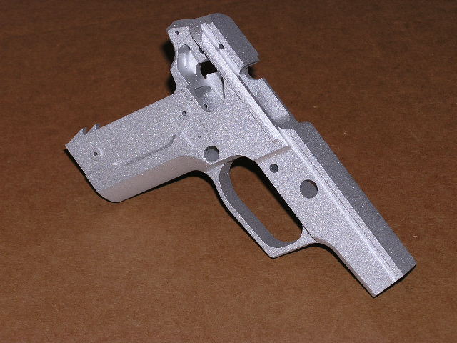
That's
the end of the 2nd operation. Here
are few better pics of what the frame
currently looks like...

I
put some of the parts on the frame to
see how it looks so far. The slide
can't slide all the way back yet because
the top of the frame isn't cut out yet,
but you should be able to get a feel for
the way it's going to look.


For
the next operation I'm going to be
cutting the mag well. I'm going to
design another fixture for this
operation. I'm going to design the
fixture so I can use it for the 3rd
operation and the 4th operation. I
hope to have this fixture designed and
machined this week, and next weekend I
should be able to get another operation
finished.
I
finally found time to work on this
project some more. I've been
really busy lately, so I haven't had
time to work on the P228 project as much
as I would have liked. But
hopefully, I'm about to be back on
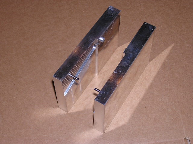
track. I got the fixtures made to
hold the frame for the rest of the
operations. The fixture that I
designed will allow me to complete the
rest of the operations without having to
machine any more special fixtures.
The fixtures have a boss that will fit
in the take down lever hole in the
frame. I also drilled 2 holes on
each of the fixtures. These holes
will allow me to locate the correct
angle for the rest of the setups.
Below you will see some pics of the
fixture...


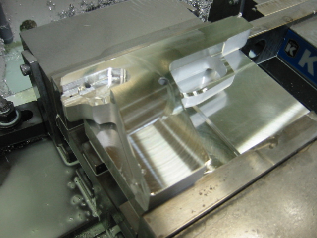
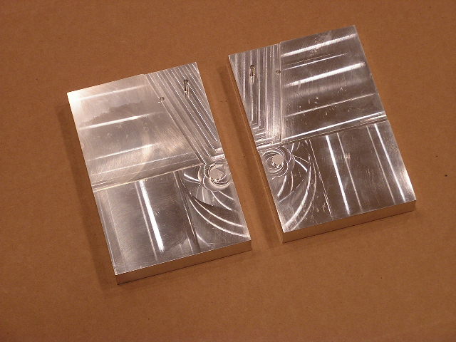
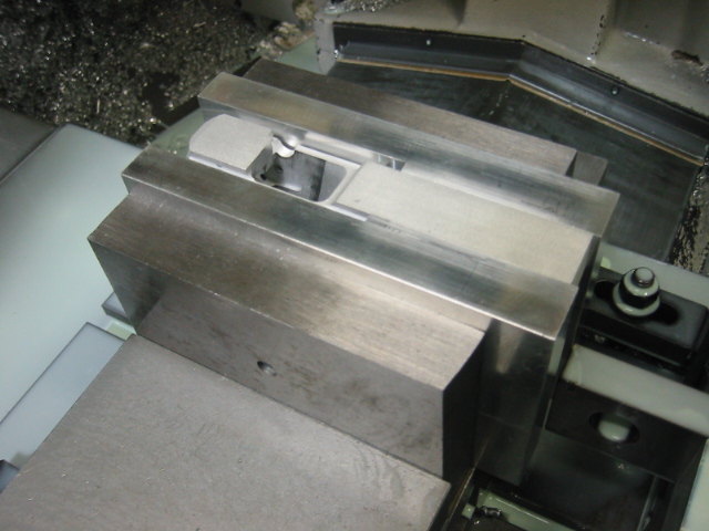
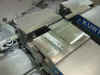
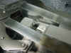
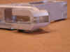
For
the 3rd operation I machined the
bottom of the mag well. The mag
well is pretty tuff to do since it is so
deep. There was no way that I
could machine the whole mag well at one
time, so I machined half of it on the
3rd operation, and I'm going to finish
machining the top of the mag well on the
4th operation. The ideal thing to
do, would be to use a wire EDM
machine. But since I don't have
access to a wire machine, I'm having to
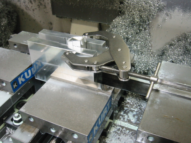
machine the mag well out. After
the mag well is finished being machined,
I will have to use a file to file out
the corners from the back of the mag
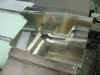
well. Below you will see pics of
the setup that I used. The pics
are after I had already ran the 1/2 hog
endmill...

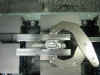
I
had to buy a super long 1/2 hog endmill
to reach all the way down inside the mag
well. I machined down to a depth
of 2.5" After I had the mag
well roughed out, I used a 4" long
3/8 carbide endmill to make the finish
passes down inside the mag
well. I bought a 6"
long 23/64 drill to drill out most of
the material down inside the mag
well. I tried this on the first
frame, but I had problems with the
drill, so I decided to just use the
super long 1/2 hog endmill to remove all
the material. Come to find out,
this was better since I'm no longer
having to worry about the long drill
"walking" off position.
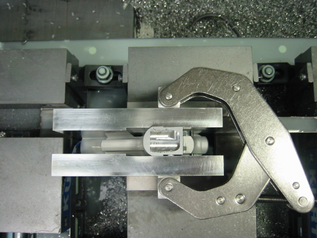
Below you will see a pic after the
bottom of the mag well was finished
being machined...
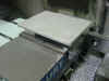
Below
you will see a better pic after the 3rd
operation...
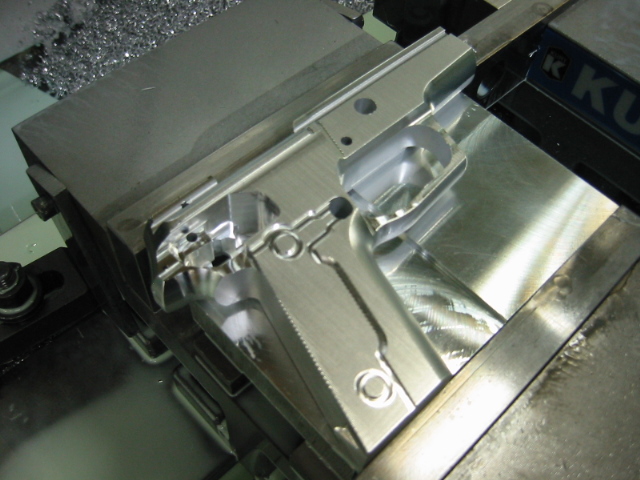
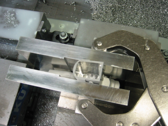
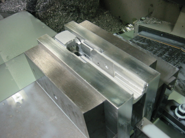
For
the 4th operation, I machined the
top of the mag well. I used the
same endmills on this operation as what
I used on the 3rd operation. I
first used a regular length 1/2"
hog endmill to remove the material as
deep as I could, and then I went back
with the long 1/2" hog endmill to
remove the rest of the material.
Finally, I used the long 3/8"
carbide endmill to make the finish
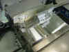
passes. Below you will see the
setup that I used...
Here's
a pic after the regular length 1/2"
hog endmill milled at a depth of
1.300" deep...
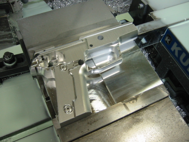
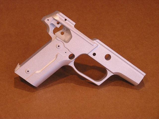
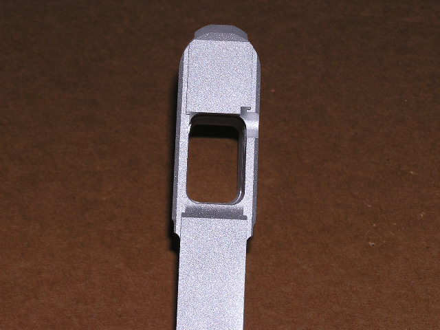
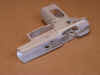
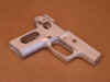
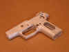
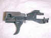
And
here's what the frame looked like after
the 4th operation was finished...
I
took some better pics to give a better
feel of the machining done so far...
The
next operation I'm going to be machining
the top of the frame. It won't be
long before I'll be putting this frame
together and shooting it for the first
time.
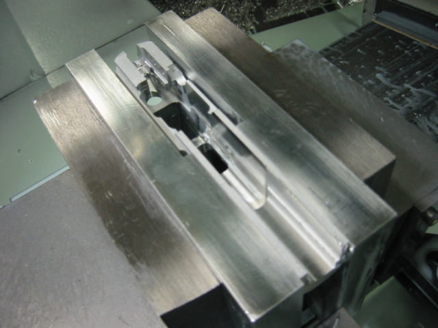
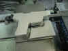
On
the 5th operation, I machined the
top of the frame. I once again
used the fixture I made for the 3rd
operation. I just moved the dowel
pins to the new location and the fixture
was ready to hold the frame horizontal
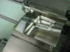
in the machining center. Here is
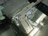
what the setup looked like...
I
used a 1/2" hog endmill to rough
out most of the material from the dust
cover area...
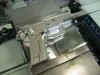
Then
I used a 1/4" carbide endmill to
mill the slot in the back of the frame
where the hammer slides in, and to mill
the slot for the trigger and some other
clean up passes. Here's a pic
after that endmill was finished...
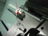
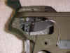
Next
I needed to mill the undercut for where
the trigger bar needs clearance inside
the frame. I was thinking I might
have to grind a special undercut tool
for this, but I got lucky and was able
to use one of the undercut tools I made
during the 1911 project. In the
pic below you can see this undercut tool
before I made the clearance cuts...
I
then used a 1/4" ball nose carbide
endmill to 3-D profile the radius inside
the dust cover. I could have used
a big 5/8" ball nose endmill, but I
though it might be quicker to just
profile this area. Here is what it
looked like after this tool...
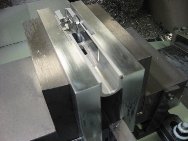
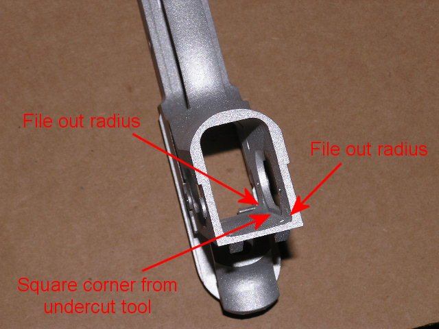
For
the 6th operation, I machined the
big slot on the side of the frame.
To cut down on the "elbow
grease" of filing the corners out
of the mag well, I used the same
undercut tool as in the 5th operation to
undercut the mag well around the big
slot. This will allow me to only
file the mag well corners out of the top
and the bottom of the mag well.
The center of the mag well will be
square from the undercut tool.
Here is a pic at the start of this
operation...
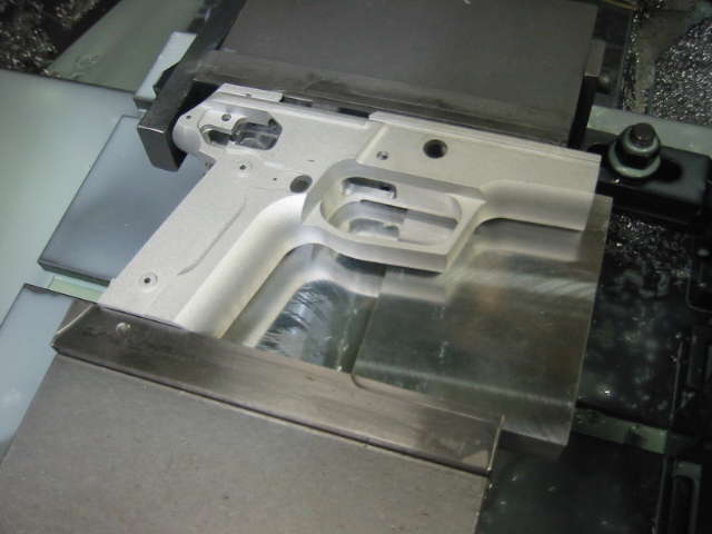
And
here is what the frame looked like after
this operation was finished...
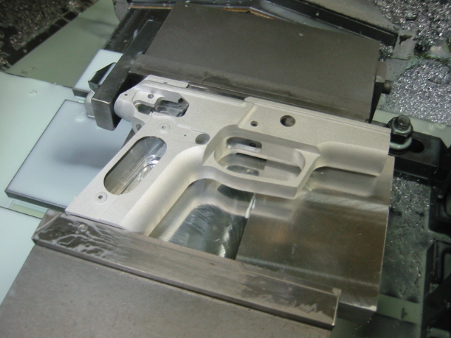
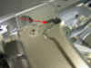
In
this pic you can see how the undercut
tool milled out the radius on this
operation...
I
once again took better pics to show the
work done so far...
I
have one other thing to machine before
this frame is finished. I have to
use a 4" diameter saw blade to
machine out the area in the back of the
frame for the clearance of the
hammer. I have this saw blade on
order, but it didn't show up in time, so
I will have to wait until it arrives to
do any more work. It should be
here next week, so by next weekend, this
frame should be finished.
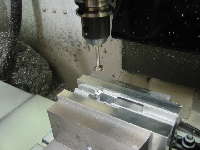
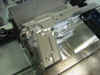
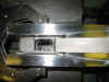
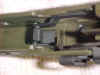
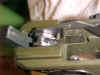
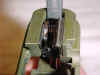
The
4" saw blade was delivered earlier
this week, and this weekend I was able
to set the frame up for the last
machining operation. The saw blade
will machine the clearance cut for the
hammer. Here is a pic of the setup
I used...
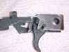
And
here I stopped the machine to take a
picture right before the 4" saw
blade went inside the frame to machine
the clearance cut...
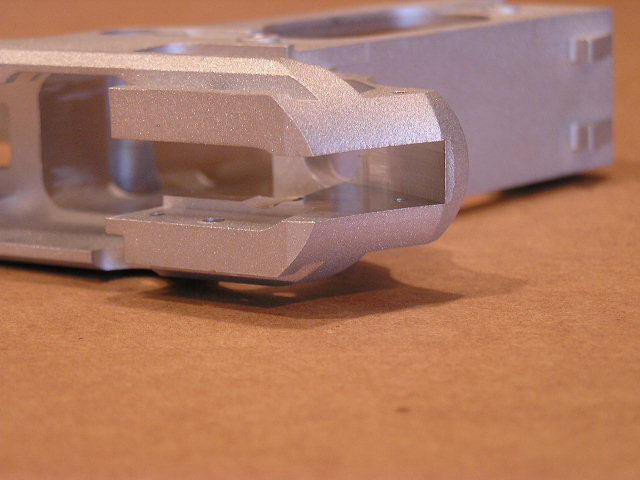
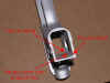
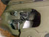
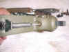
It's
hard to show exactly the cut that the
saw blade made. But maybe this
next picture will make it a little
clearer. Notice the shiny section
inside the frame...
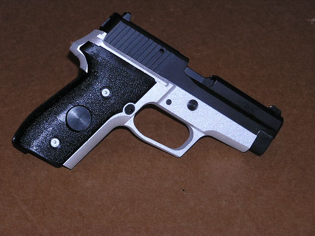
Since
I made this clearance cut, the hammer
will now slide all the way in, and the
little hammer stop part will slide all
the way in as well. The next
pictures I'll be showing will be of the
frame with all the parts
installed. Once I test fire this
pistol, I will strip the frame back down
and black anodize the frame, and
refinish some of the internal
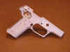
parts. Once the pistol is completely
finished, I'll take some final pictures.
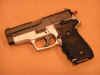
Well,
I just learned a whole lot about how the
P228 functions. The parts kit I
used was a kit from Dlask.
The parts aren't the quality as those
from SIG, but I was able to use every
single part in the kit. I've heard
of some people not being able to use all
the parts in the kit and have to end up
buying some of the parts from SIG.
Either I got lucky with my Dlask parts,
or I done more hand fitting than those
other guys. The best thing about
having to hand fit every part, is that I
was able to learn a whole lot about how
the P228 functions. The barrel I
got from FAC.
The barrel is 100% perfect. I
didn't have to modify the barrel at
all. The FAC barrel also dropped
right into my original SIG P229 that I
made the P228 model from. I have
hand cycled the P228 several times, and
it functions perfectly so far.
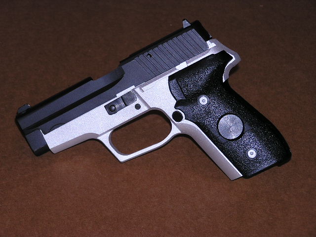
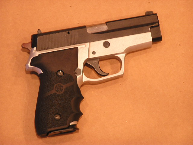
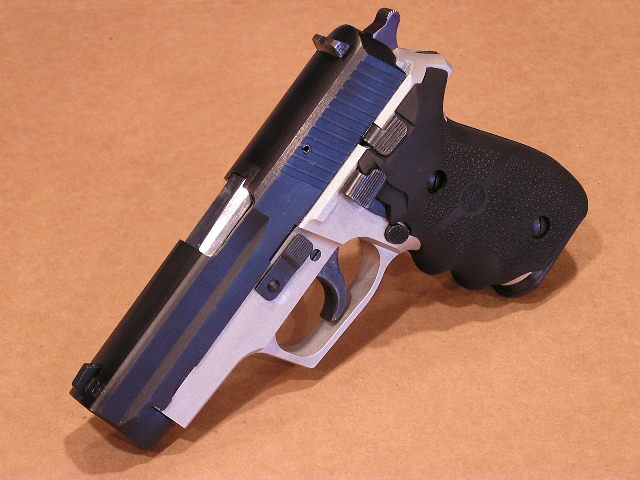
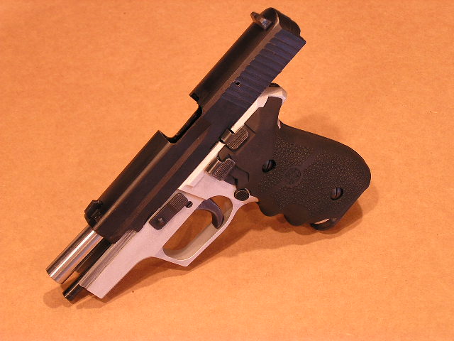
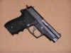
Sometime in the next week, I will find
time to take my new P228 pistol out for
her first shots. After the test
firing, and if no problems are found, I
will refinish the pistol to make it look
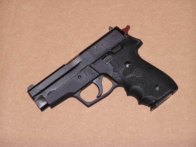
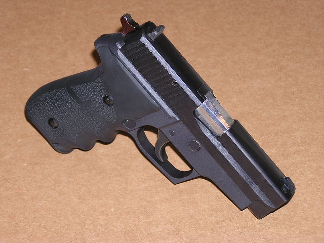
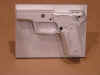
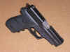
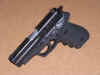
alot better. Here are a few pics
of what the pistol currently looks
like...
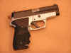

If
you don't count my time and the material
cost of the frame I made, this P228
pistol cost me $159.95 The
parts kit was $65, and the barrel was
$94.95 Not a bad deal for a P228
huh?
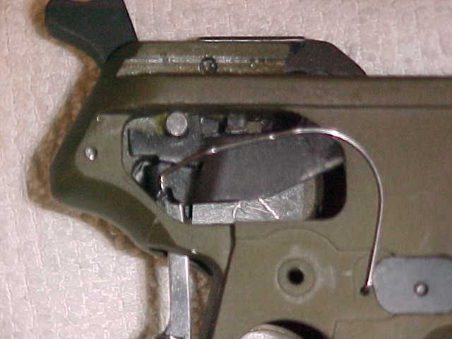
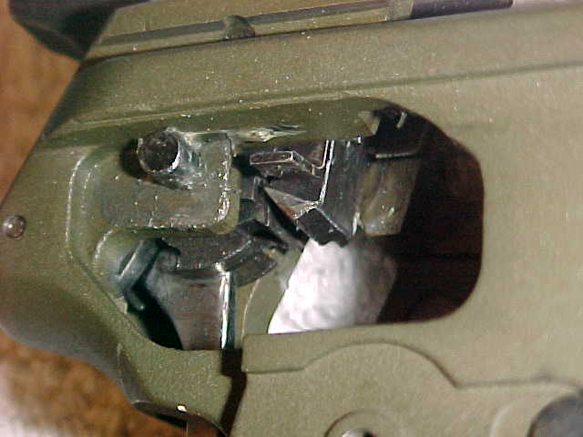
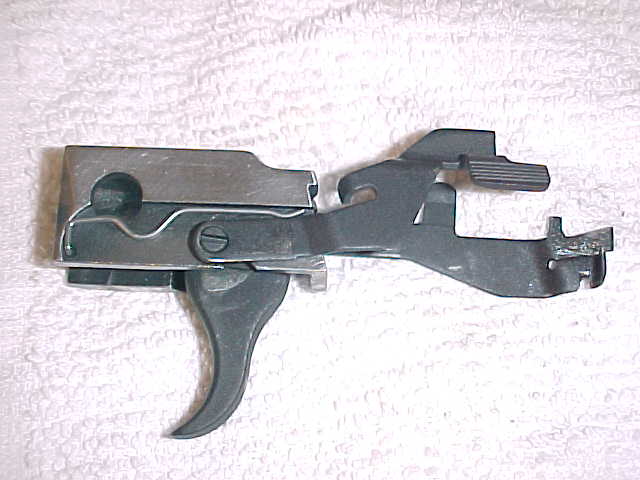
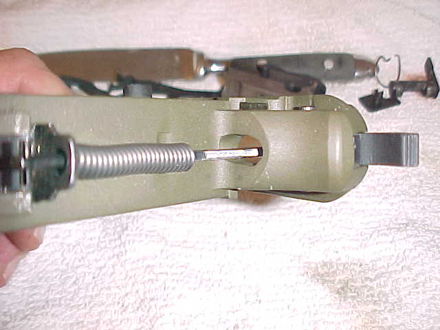
To
give you a better idea of how all the
internal parts fit together, bybon from
the Roderus forum has allowed me to post
his pictures here on my website.
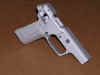
I
finally found time to test fire the
pistol. I first tried to use the
magazine that came with the Dlask parts
kit. I heard of a few people
having problems with these mags, so I
took along my SIG P229 mag just in case
I had problems. After I shot the
first round using the Dlask mag, it
jammed on me. I think the problem
with the Dlask mag is that it doesn't
have enough spring force to feed the
next round. I loaded the SIG P229
mag up, and fired one full mag with no
problems at all. I loaded the mag
up again, and still no problems. I
ended up shooting about 50 rounds with
the SIG P229 mag with out one
problem. I didn't want to shoot
the pistol any more since it was still
just raw aluminum, and I was afraid the
steel slide would wear down the
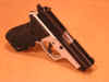
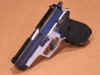
frame. After I got home, I cleaned
the pistol and stripped it back down to
the bare frame. I took the frame
to the shop and bead blasted it one last
time and then black anodized it. I
thought it came out really good. I
was going to re-parkerize some of the
Dlask parts, but I think I'm just going
to leave the parts the way they are for
now. I may re-finish the hammer
and the trigger, so at least those 2
parts will look a little better. I
put the pistol back together and below
are a few pics of what the pistol looks
like finished...

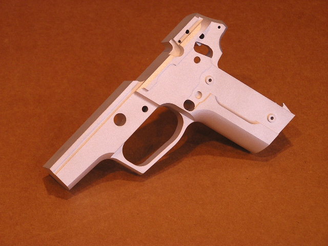
Since
I know the solid model that I created of
this frame is good, the solid model file
and the SolidWorks E-drawing file is now
available for download. I hope you
enjoyed this project as much as I
have.