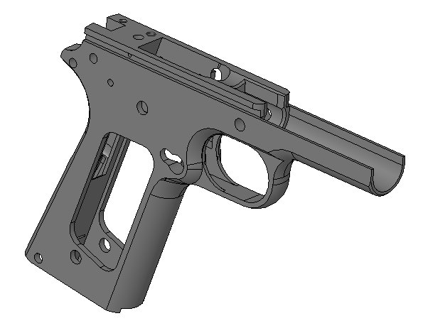
1911 A-1 Frame

After working on the rifles, I thought it was time to try a pistol. After looking over the Roderus forum, I saw a bunch of guys doing custom work on the 1911 pistol. I wanted to do some of the same custom work one day, but I first needed to make a frame. After doing some searching, I found the 1911 solid model (the CAD file). After finding this model, I had a big first step out of the way. I bought a Wilson Combat 1911 frame to use as a reference while I done the machining. This way I could look at the physical frame and get a better idea of how I needed to machine each feature. After I had my game plan together, I started making the program to make the frame (the CAM part). Of course I was going to be starting from a block of material (billet), so I knew there would be a lot of machining required. Come to find out, this project became more complicated that what I had expected. But I stuck with it, and was able to finish the 1911 frame.
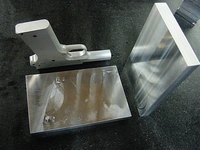
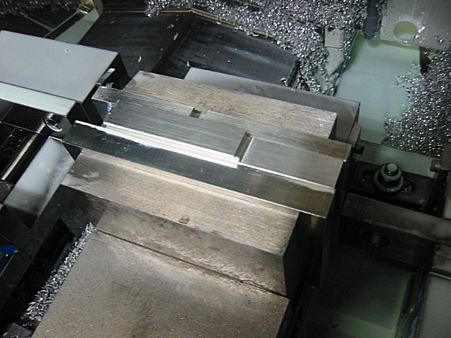
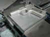
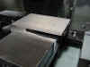
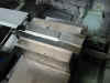
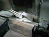
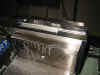
On the 1st operation I took a picture to show what the block of aluminum looked like that I started with and the Wilson Combat frame...
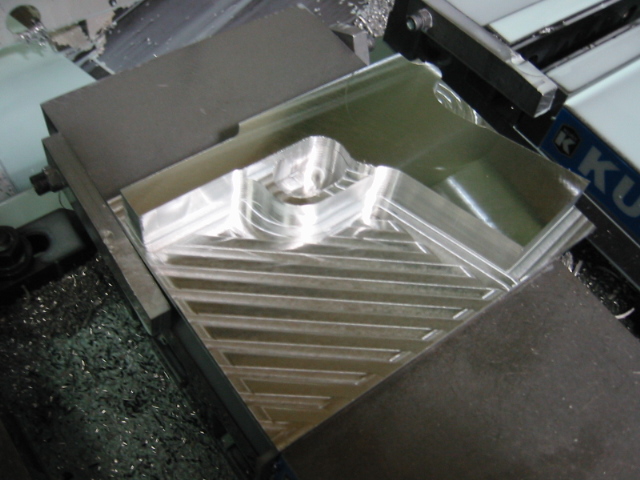
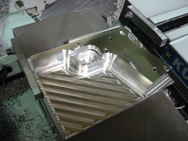
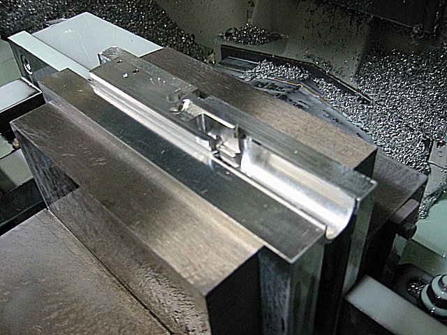
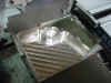
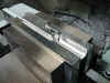
There was a lot of material to be removed to get the basic shape of the frame. Here is what the frame looked like after it was roughed out...
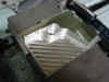
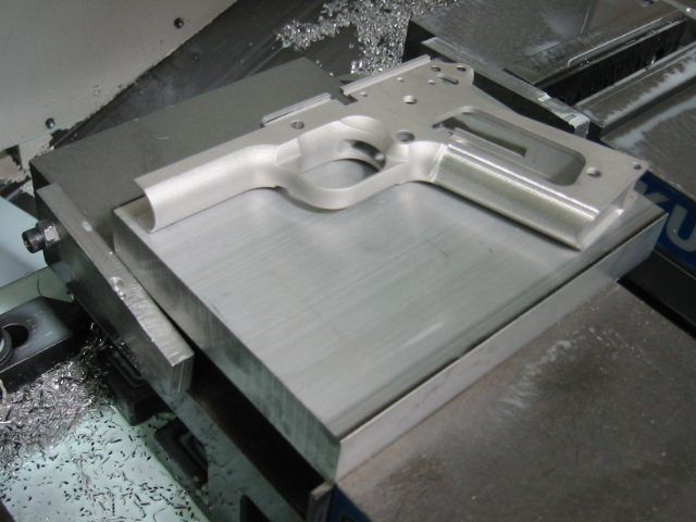
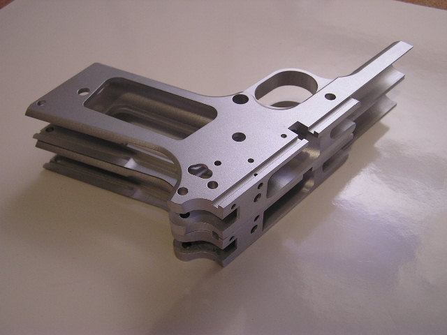
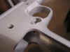
This is a pic after the 1st operation was finished. It actually looks kinda like a pistol frame after this operation...
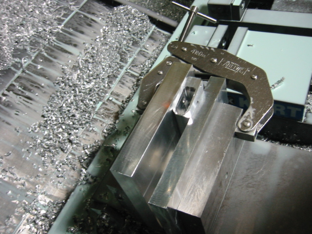
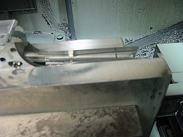
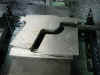
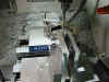
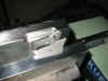
In order to hold the frame for the 2nd operation, I had to make a special set of jaws for the vice so I could clamp onto as much of the frame as possible. Here is what the jaws looked like...
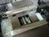
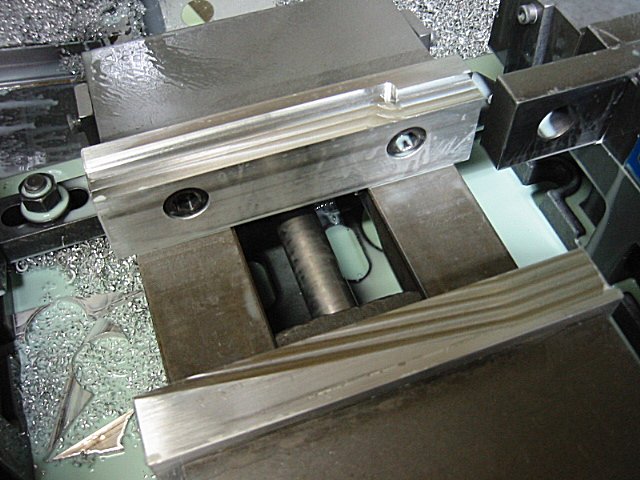
Here is what the frame looked like clamped into the jaws I made...
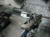
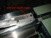
I cut off the excess material around the frame...
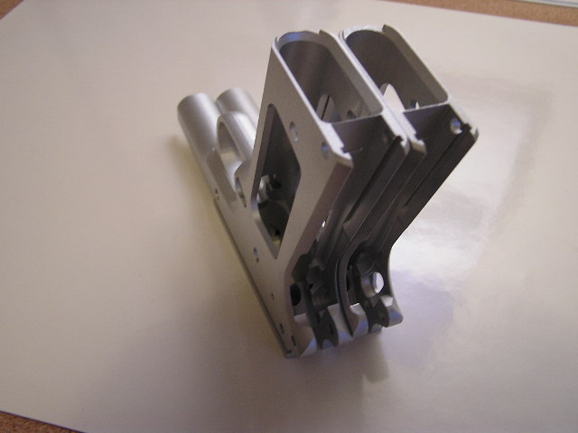
And here is what the frame looked like after the 2nd operation was finished...
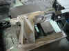
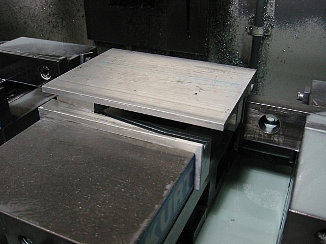
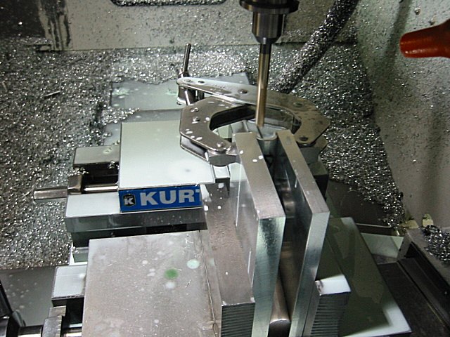
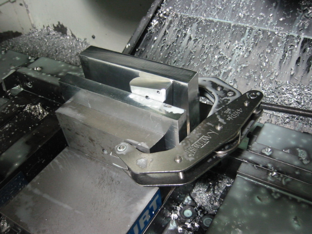
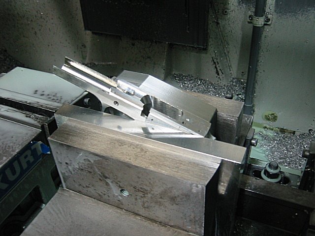
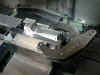
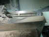
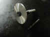
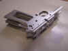
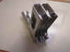
I had to make a special fixture so I could hold the frame for the 3rd operation. This is what it looked like...
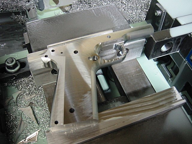
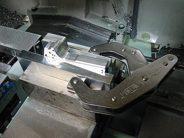
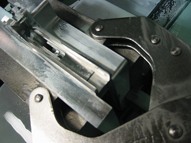
Here is what the frame looked like when it and the fixture was clamped into the vice...
And here's the frame after the 3rd operation...
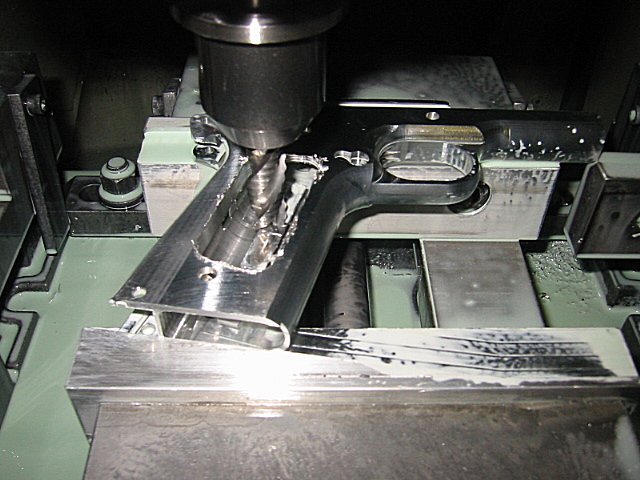
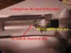
The 4th operation I finished milling down inside the dust cover. It's hard to see the machining I done on this operation, but you can get an idea of how long of an endmill I had to use...
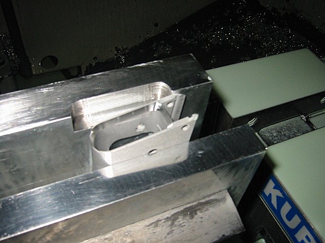
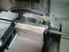
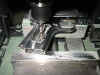
For the 5th operation I done the bottom half of the magazine (mag) well. I machined the mag well in two steps, kinda like I did the AR-15 mag well. I first done the bottom half, and then machined the top half. This worked out a lot easier than trying to machine the whole mag well out at one time. This is what the setup looked like...
And here's the frame after the 5th operation was finished...
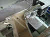
On the 6th operation I finished cutting the mag well from the top. You can see another set of special fixtures I had to make in order to hold the frame at the correct angle...
Here is what the frame looked like after the 6th operation was finished...
For the 7th operation I cut the back side of the frame where the main spring housing fits. Here's the setup...
It's hard to tell from this picture what machining was done, but maybe you can get an idea...

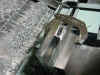
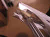
This operation I had to make some special undercut tools to machine underneath where the hammer fits. Here you can see the special tools I had to grind...
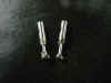
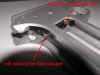
On the 8th operation I machined the undercut slot where the main spring housing slides into the frame. Here is what it looked like...
The 9th operation I machined the undercut for the mag catch lock that keeps the mag release in place. This is a really bad picture, but maybe you can see the undercut I made...
On this operation I also machined out the big slot through the mag well...
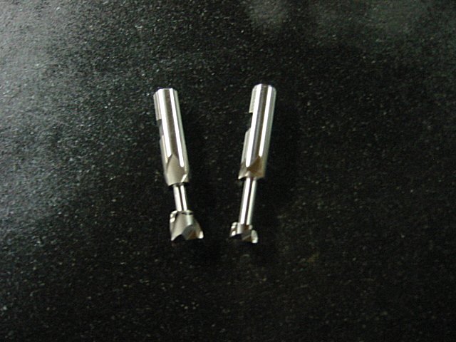
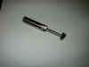
Here's a picture of the undercut tool I made for the mag catch lock...
Here is a good picture of what the frame looked like after this operation...
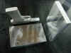
For the 10th operation, I was going to make a saw cut and an undercut. The saw cut will be for the inside of the frame where the clearance is needed for the hammer. And the undercut is for underneath the thumb safety. Here are the tools I used...
Here's a good pic of what the frame looked like after this operation...
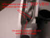
The 11th operation I machined "as much as possible" of the trigger bow that's down inside the mag well. You can't tell what was machined on this operation from this pic, but you can see how I set it up...
And here you can see another special undercut tool I had to make to machine this section of the trigger bow...
For the 12th operation, I set the frame up so I could machine (from the back side) down inside the frame to finish cutting as much as I could of the trigger bow. Here's a pic of the setup...

After this operation I took some pictures to show just what I had done. There is no way to completely machine all of the trigger bow, so I'll have to do some filing to remove the extra material. I think most companies use a broach to finish removing this material, but since I didn't access a broach, I finished it the ol' fashion way, with a hand file. I will let these pictures speak for themselves...
For the 13th operation, I machined the chamfer around the bottom of the mag well...
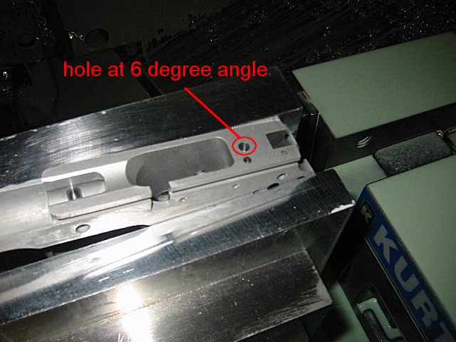
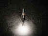
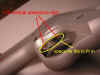
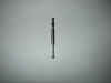
Finally the last operation! The 14th operation. In this operation I drilled the hole on top of the frame that is at a 6 degree angle. This hole is for the disconnector. This hole has an undercut, so I once again had to make an undercut tool to plunge inside the hole to make the cut. I've never done anything where it had to have so many undercut tools. Here's a pic of the setup...
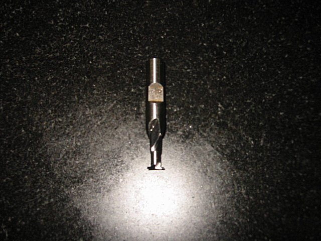
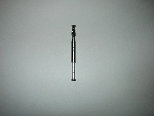
And here's a pic of the undercut tool...
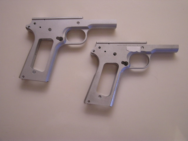
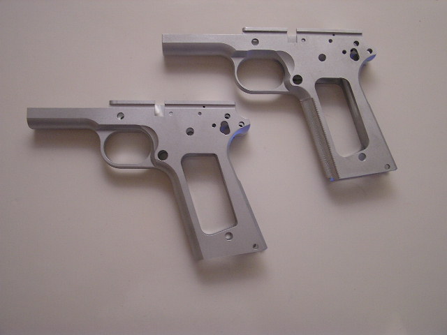
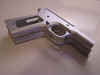
Here are a few pics of what my final frame looked like compared to the Wilson Combat frame that I bought...
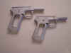
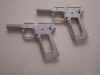
Can you tell which frame is which?
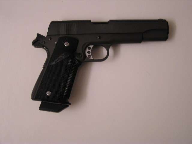
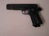
Since this was my first 1911 build I didn't want to use expensive parts since I knew I would probably make a mistake putting everything together (after all I'm not a gunsmith). So I bought a cheap parts kit from Sarco. Come to find out the quality of parts from Sarco wasn't all the great, so I done a lot of learning about how everything fit together, and how to custom fit the parts. Luckily I didn't have to scrap any of the parts. I put a new finish on all the parts and hard anodized the frame. I still need to install a rear sight on the slide, but I can do that at a later time. Here are some final pics of my 1911 project...

Here are a few of illustrations of how the 1911 functions...
The
link below is also a really cool
interactive demonstration of how the
1911 pistol works. This is a link
from the www.m1911.org
website. You can click on the
boxes on the left and it will turn on
and off the different parts of the
pistol. Check it out.

I hope you have enjoyed this project. It was a whole lot of work, but I think it was well worth it. I hope all my future projects are easier than what this one was. I think other projects could only be down hill from having done this project.